Pilot Signal Allocation Method and Apparatus

a pilot signal and allocation method technology, applied in the field of pilot signal allocation, can solve the problems of limited number of separable pilot signals available, restrictions on the format of pilot symbols,

Inactive Publication Date: 2009-07-02
GOOGLE TECH HLDG LLC
View PDF4 Cites 111 Cited by
  • Summary
  • Abstract
  • Description
  • Claims
  • Application Information

AI Technical Summary

Problems solved by technology

This leads to restrictions on the pilot symbol format.
However, there are a limited number of separable pilot signals available for use by different transmitters in the system.

Method used


Image

  • Pilot Signal Allocation Method and Apparatus
  • Pilot Signal Allocation Method and Apparatus
  • Pilot Signal Allocation Method and Apparatus

Examples


Embodiment Construction

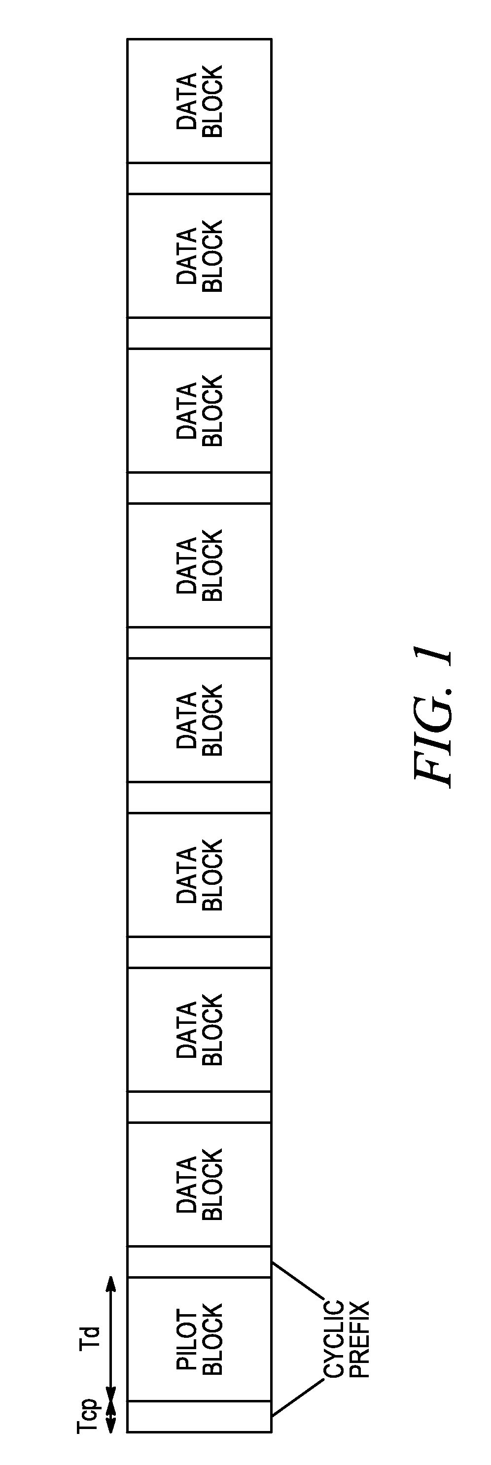
[0026]To address the above-mentioned need, a method and apparatus for pilot or reference signal allocation is disclosed herein. In particular, a pilot (or reference) allocation scheme is utilized where different transmitters are assigned pilot sequences with possibly different cyclic time shifts and possibly different block orthogonal codes over a plurality of pilot blocks. A pilot signal is transmitted concurrently by the transmitters in a plurality of pilot blocks, and a receiver processes the plurality of received pilot blocks to recover a channel estimate for at least one of the transmitters while suppressing the interference due to the pilot signals from the other transmitters.

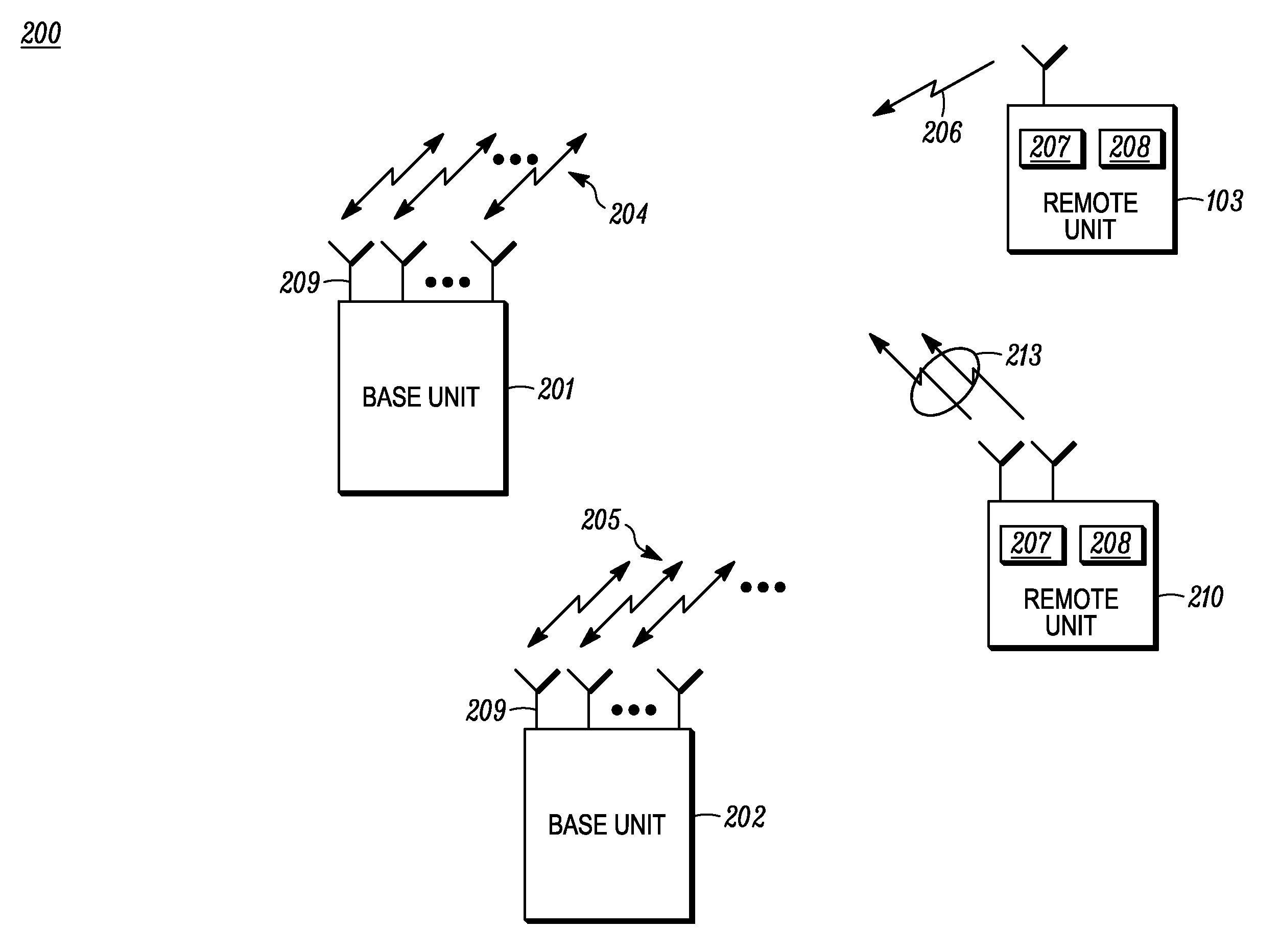
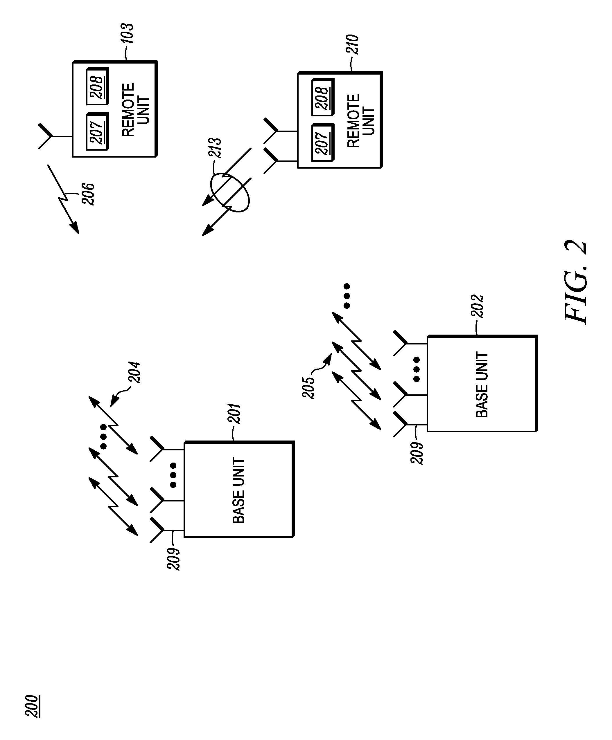
[0027]Turning now to the drawings, where like numerals designate like components, FIG. 2 is a block diagram of communication system 200 that utilizes pilot transmissions. Communication system 200 preferably utilizes either OFDMA or a next generation single-carrier based FDMA architecture for uplink transm...


PUM


Abstract

A pilot (or reference) transmission scheme is utilized where different transmitters are assigned pilot sequences with possibly different cyclic time shifts and different base pilot sequences. A pilot signal is transmitted concurrently by the transmitters in a plurality of pilot blocks, and a receiver processes the plurality of received pilot blocks to recover a channel estimate for at least one of the transmitters while suppressing the interference due to the pilot signals from the other transmitters.

Description

FIELD OF THE DISCLOSURE[0001]The present invention relates generally to pilot signal allocation, and in particular to a method and apparatus for pilot signal allocation in a communication system.BACKGROUND OF THE DISCLOSURE[0002]A pilot signal (or reference signal) is commonly used for communication systems to enable a receiver to perform a number of critical functions, including but not limited to, the acquisition and tracking of timing and frequency synchronization, the estimation and tracking of desired channels for subsequent demodulation and decoding of the information data, the estimation and monitoring of the characteristics of other channels for handoff, interference suppression, etc. Several pilot schemes can be utilized by communication systems, and typically comprise the transmission of a known sequence at known time intervals. A receiver, knowing the sequence only or knowing the sequence and time interval in advance, utilizes this information to perform the abovementione...

Claims


Application Information

Patent Timeline
Patent Type & Authority Applications(United States)
IPC IPC(8): H04J3/00
CPCH04L5/0007H04L5/0037H04L5/0051H04L27/2613H04L25/0228H04L25/03159H04L27/2607H04L5/0091
Inventor BAUM, KEVIN L.CLASSON, BRIAN K.NANGIA, VIJAY
Owner GOOGLE TECH HLDG LLC
Why Eureka
Try Eureka