
Method and System for Utilizing Transmit Local Oscillator for Improved Cell Search and Multi-Link Communication in Multi-Mode Device

a multi-mode device and transmit local oscillator technology, applied in the field of wireless cellular communication devices, can solve the problems of repeated interruptions in communication, limited lime and resource resources, and radio access technologies such as wlan or wan, which do not intrinsically support mobility and soft handoffs

Active Publication Date: 2009-07-02
GOOGLE TECH HLDG LLC
View PDF8 Cites 84 Cited by
  • Summary
  • Abstract
  • Description
  • Claims
  • Application Information

AI Technical Summary

Benefits of technology

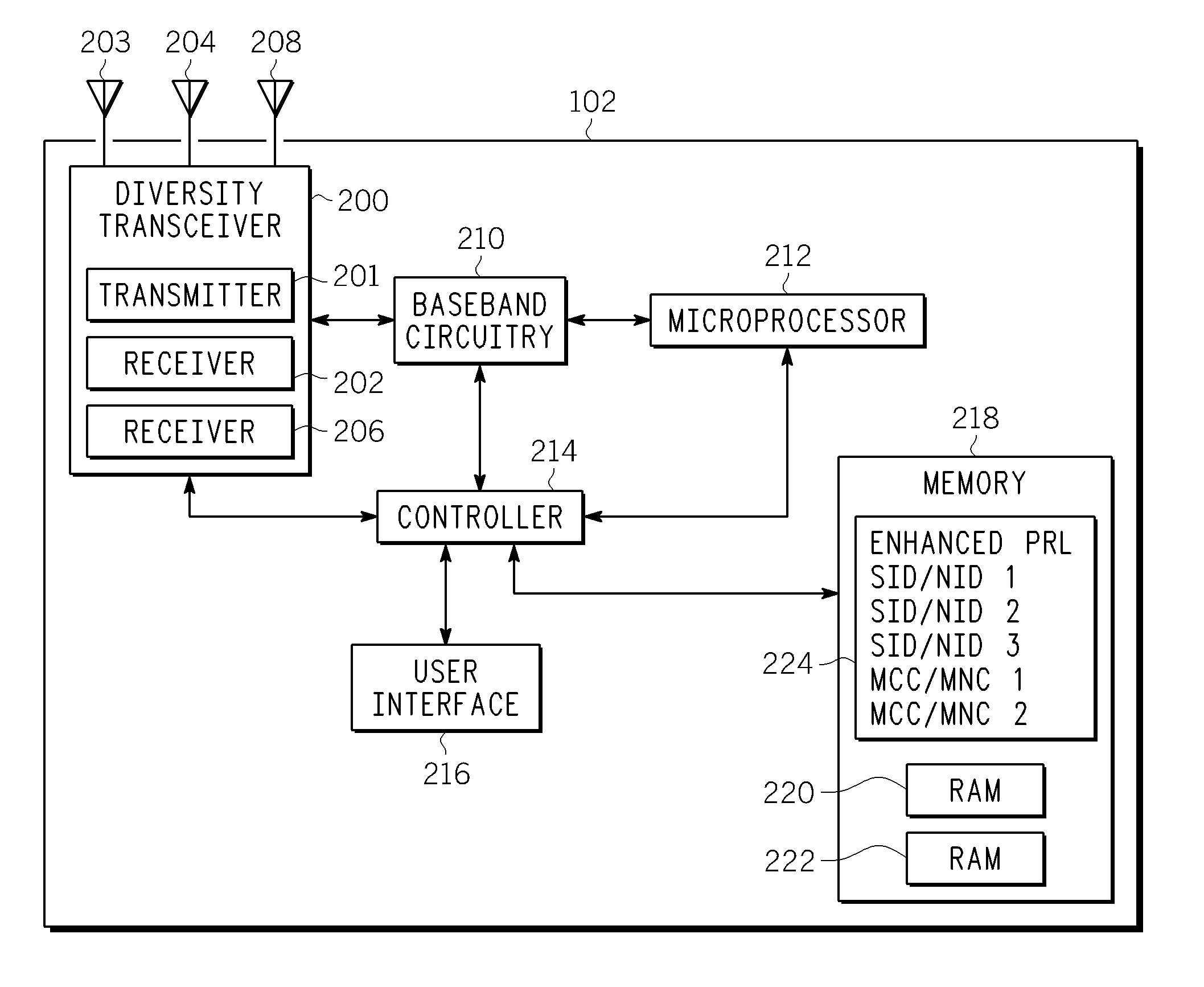
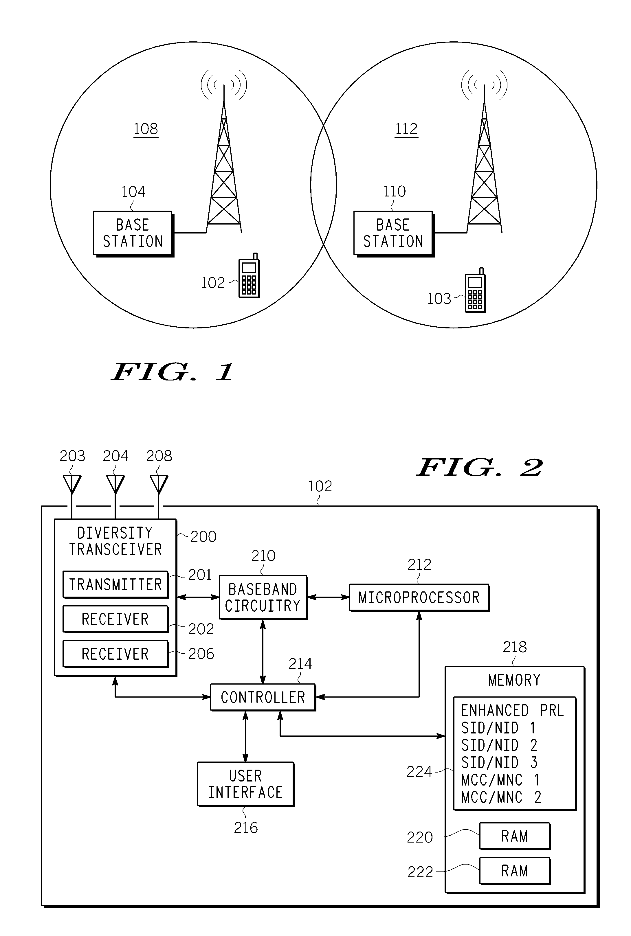
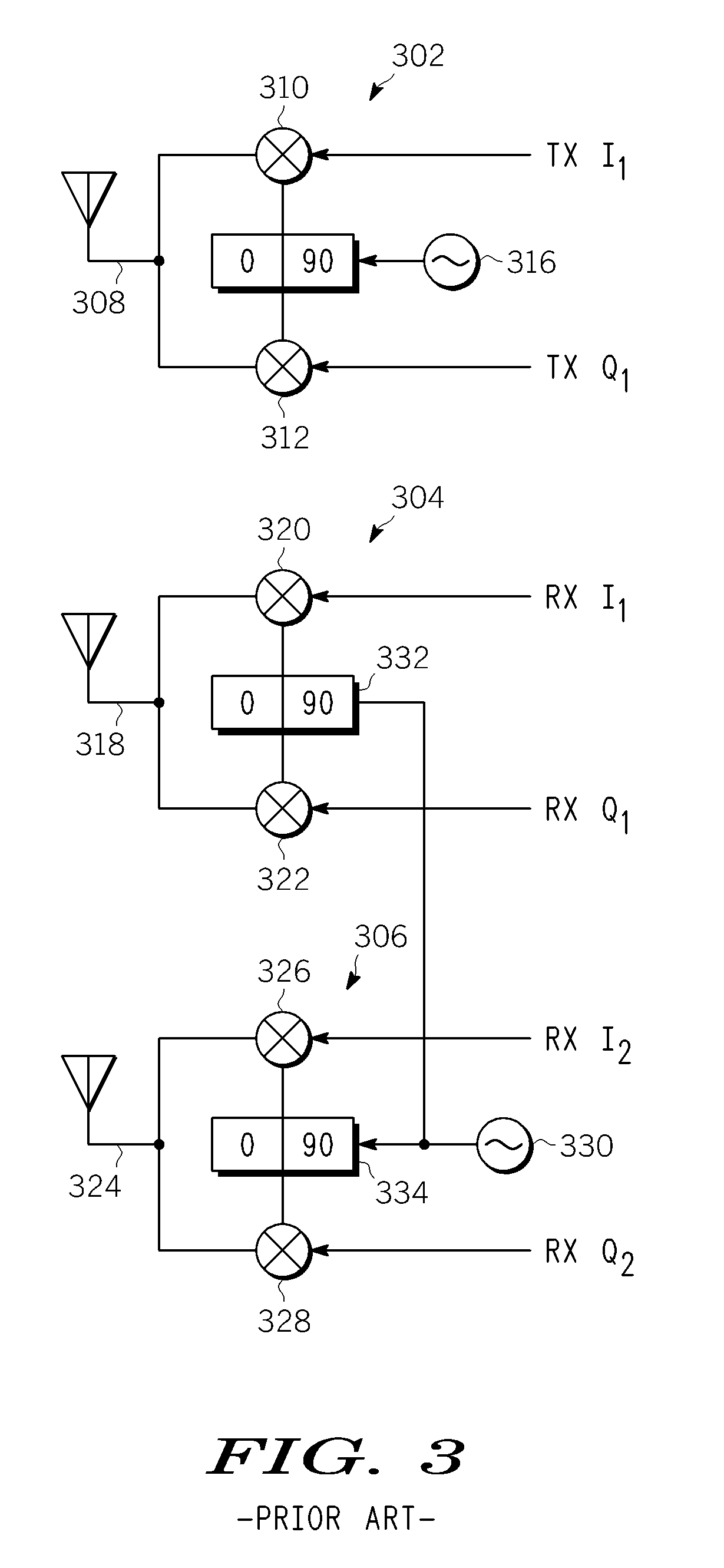
[0008]The present invention, according to an embodiment, provides a novel and efficient multi-receiver wireless communication device that includes a transmitter, a transmit oscillator communicatively coupled to the transmitter, a receive oscillator communicatively coupled to a first receiver and second receiver, and a switching assembly having a first state in which the receive oscillator is coupled to the first and second receivers and a second state in which the receive oscillator is de-coupled from the second receiver and the transmit oscillator is coupled to the second receiver. The first receiver and the second receiver of the wireless communication device are able to operate independent of one another when the switching assembly is in the second state.

Problems solved by technology

This often leads to repeated interruptions in communication.
This is a lime and resource limited process.
Unfortunately, some radio access technologies such as WLAN or WAN, do not intrinsically support mobility and soft handoffs.
Due to these technology limitations, prior art equipment can degrade the user experience.
However, these receivers can not always be operated independently due to performance gains associated with receive diversity, interference cancellation, or two-port MIMO operation.
The addition of a second receive LO to the WCD for the purpose of measuring other frequencies is not desirable from a complexity and cost standpoint.

Method used


Image

  • Method and System for Utilizing Transmit Local Oscillator for Improved Cell Search and Multi-Link Communication in Multi-Mode Device
  • Method and System for Utilizing Transmit Local Oscillator for Improved Cell Search and Multi-Link Communication in Multi-Mode Device
  • Method and System for Utilizing Transmit Local Oscillator for Improved Cell Search and Multi-Link Communication in Multi-Mode Device

Examples


Embodiment Construction

[0032]As required, detailed embodiments of the present invention are disclosed herein; however, it is to be understood that the disclosed embodiments are merely exemplary of the invention, which can be embodied in various forms. Therefore, specific structural and functional details disclosed herein are not to be interpreted as limiting, but merely as a basis for the claims and as a representative basis for teaching one of ordinary skill in the art to variously employ the present invention in virtually any appropriately detailed structure. Further, the terms and phrases used herein are not intended to be limiting; but rather, to provide an understandable description of the invention. While the specification concludes with claims defining the features of the invention that are regarded as novel, it is believed that the invention will be better understood from a consideration of the following description in conjunction with the drawing FIGS., in which like reference numerals are carrie...


PUM


Abstract

A multi-receiver wireless communication device includes a transmitter, a transmit oscillator communicatively coupled to the transmitter, a receive oscillator communicatively coupled to a first receiver and second receiver, and a switching assembly having a first state in which the receive oscillator is coupled to the first and second receivers and a second state in which the receive oscillator is de-coupled from the second receiver and the transmit oscillator is coupled to the second receiver. The first receiver and the second receiver of the wireless communication device are able to operate independent of one another when the switching assembly is in the second state.

Description

BACKGROUND OF THE INVENTION[0001]1. Field of the Invention[0002]This invention relates in general to wireless cellular communication devices capable of multiple-input, multiple-output (MIMO) communication and / or receive diversity and, more particularly, to utilizing the transmit local oscillator (LO) to drive a receiver when the transmitter in not in use.[0003]2. Description of the Related Art[0004]A wireless communication device (WCD), such as a cellular telephone, for instance, is required to utilize multiple radio access technologies and multiple frequency bands when performing measurement and synchronization on communication cells. This occurs in the transition from switch-on to camp-on when locating the best cell on the best network and is maintained in Idle mode and in Dedicated mode. Although the WCD must cycle through the multiple radio access technologies and multiple bands, the operator (and end-user) desires a fast reaction time as the radio conditions change.[0005]In a m...

Claims


Application Information

Patent Timeline
IPC IPC(8): H04B7/02H04B1/44
CPCH04B1/403H04B7/0874H04B7/0871H04B1/44
Inventor CHANCE, GREGORY W.BATEMAN, DAVIDBOIXADERA, FRANCESCHARROLD, WILLIAM B.KLOMSDORF, ARMIN W.MUCK, MARKUSMUSIC, WAYNE D.
Owner GOOGLE TECH HLDG LLC
Learn More