
Multi-link segmentation and reassembly for bonding multiple PVC's in an inverse multiplexing arrangement

a multi-link segmentation and reassembly technology, applied in the field of private computer networks, can solve problems such as actual delay variation, bandwidth waste, congestion,

Inactive Publication Date: 2002-12-03
ATWATER PARTNERS LLC OF TEXAS
View PDF7 Cites 37 Cited by
  • Summary
  • Abstract
  • Description
  • Claims
  • Application Information

AI Technical Summary

Benefits of technology

Multi-link segmentation and reassembly for bonding multiple permanent virtual circuits in an inverse multiplexing arrangement, representing an embodiment of the invention, can be cost effective and advantageous for at least the following reasons. The invention can provide statistically significant performance data relating to the host ATM system, as well as specific routing configurations thereof. The invention improves quality and / or reduces costs compared to previous approaches.All the disclosed embodiments of the invention disclosed herein can be made and used without undue experimentation in light of the disclosure. Although the best mode of carrying out the invention contemplated by the inventors is disclosed, practice of the invention is not limited thereto. Accordingly, it will be appreciated by those skilled in the art that the invention may be practiced otherwise than as specifically described herein. Further, the individual components need not be combined in the disclosed configurations, but could be combined in virtually any configuration.Further, although the multi-link segmentation and reassembly for bonding multiple permanent virtual circuits in an inverse multiplexing arrangement described herein can be a separate module, it will be manifest that the time-delay measurements, time-delay variance measurements and cell transfer rate measurements in asymmetric transfer mode networks may be integrated into the system with which they are associated. Furthermore, all the disclosed elements and features of each disclosed embodiment can be combined with, or substituted for, the disclosed elements and features of every other disclosed embodiment except where such elements or features are mutually exclusive.It will be manifest that various substitutions, modifications, additions and / or rearrangements of the features of the invention may be made without deviating from the spirit and / or scope of the underlying inventive concept. It is deemed that the spirit and / or scope of the underlying inventive concept as defined by the appended claims and their equivalents cover all such substitutions, modifications, additions and / or rearrangements.The appended claims are not to be interpreted as including means-plus-function limitations, unless such a limitation is explicitly recited in a given claim using the phrase(s) "means for" and / or "step for." Subgeneric embodiments of the invention are delineated by the appended independent claims and their equivalents. Specific embodiments of the invention are differentiated by the appended dependent claims and their equivalents.

Problems solved by technology

A problem with this technology has been that the bandwidth is wasted when there is no data available for transmission.
The Service Provider network is unaware of such idle data fill-in units and the associated bandwidth is thus required to transport such useless data across the cloud.
The drawback is that at times of peak loading, congestion could occur.
The presence of buffers introduces delay, and the statistical nature of traffic causes the actual delay to vary about some nominal mean value.
Problems with current ATM technology include bandwidth constraints, which represent a significant limitation during times of peak network congestion.
Another problem with the current technology is the instability of the communication links during dynamic reconfiguration between paths of different lengths.
Heretofore, the requirements of providing a flexible point-to-point potential bandwidth increase over an asymmetric transfer mode network link, and stabilizing communication links during dynamic reconfiguration between paths of different lengths referred to above have not been fully met.

Method used


Image

  • Multi-link segmentation and reassembly for bonding multiple PVC's in an inverse multiplexing arrangement
  • Multi-link segmentation and reassembly for bonding multiple PVC's in an inverse multiplexing arrangement
  • Multi-link segmentation and reassembly for bonding multiple PVC's in an inverse multiplexing arrangement

Examples


Embodiment Construction

The invention and the various features and advantageous details thereof are explained more fully with reference to the nonlimiting embodiments that are illustrated in the accompanying drawings and detailed in the following description. Descriptions of well known components and processing techniques are omitted so as not to unnecessarily obscure the invention in detail. It should be understood, however, that the detailed description and the specific examples, while indicating preferred embodiments of the invention, are given by way of illustration only and not by way of limitation. Various substitutions, modifications, additions and / or rearrangements within the spirit and / or scope of the underlying inventive concept will become apparent to those skilled in the art from this detailed description.

Within this application one or more publications are referenced by Arabic numerals within parentheses or brackets. Full citations for these, and other, publications may be found at the end of ...


PUM


Abstract

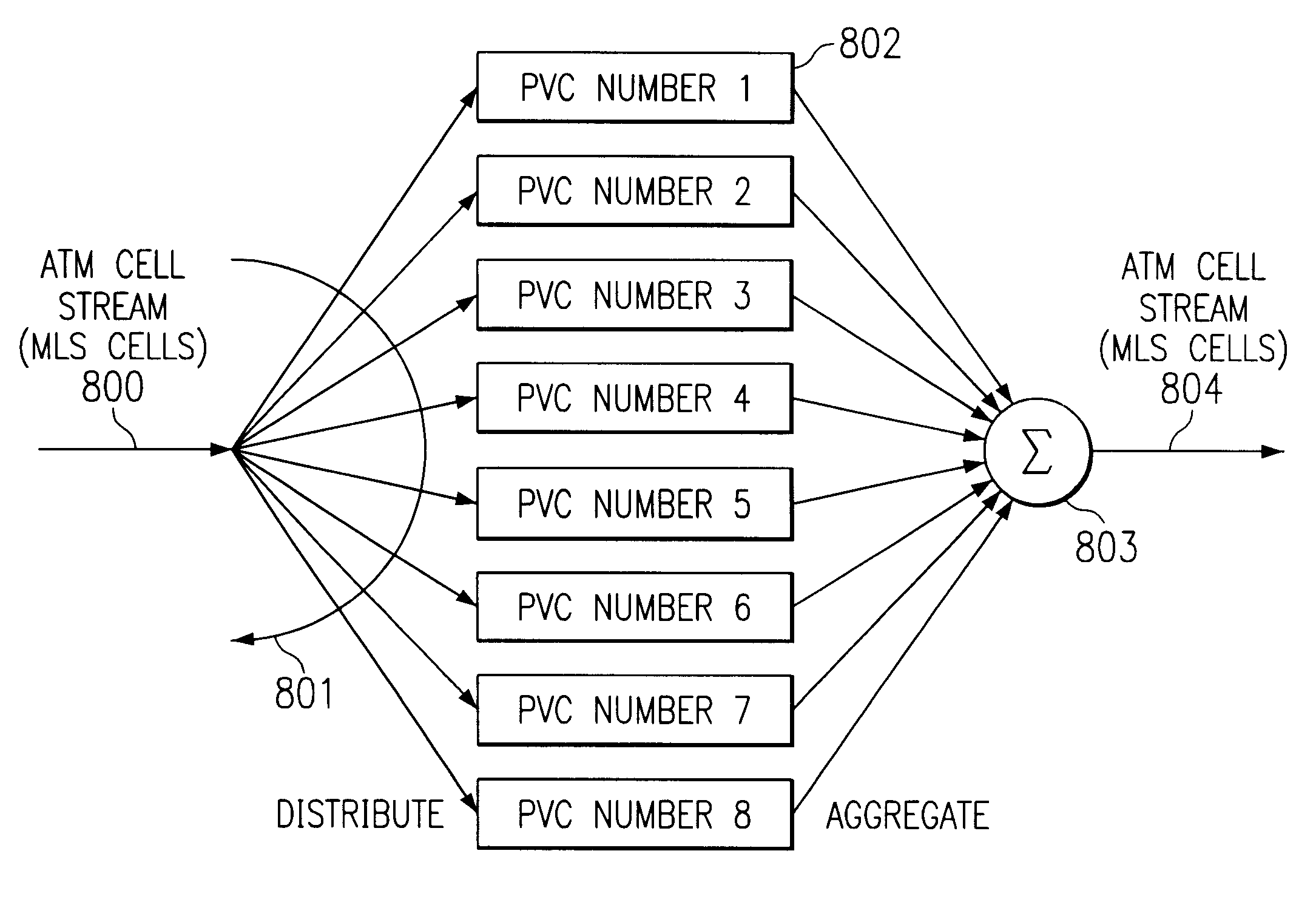
Systems and methods are described for multi-link segmentation and reassembly for bonging multiple virtual circuits in an inverse multiplexing arrangement. A method includes: generating a plurality of multilink segmentation and reassembly sublayer cells at a first location; distributing the plurality of multilink segmentation and reassembly sublayer cells across a plurality of virtual circuits; transmitting the plurality of multilink segmentation and reassembly sublayer cells to a second location via the plurality of virtual circuits; and receiving the plurality of multilink segmentation and reassembly sublayer cells at the second location. An apparatus includes a multilink segmentation and reassembly sublayer transmitter, including: a source buffer; a multilink controller coupled to the source buffer; and a plurality of virtual circuits coupled to the multilink controller.

Description

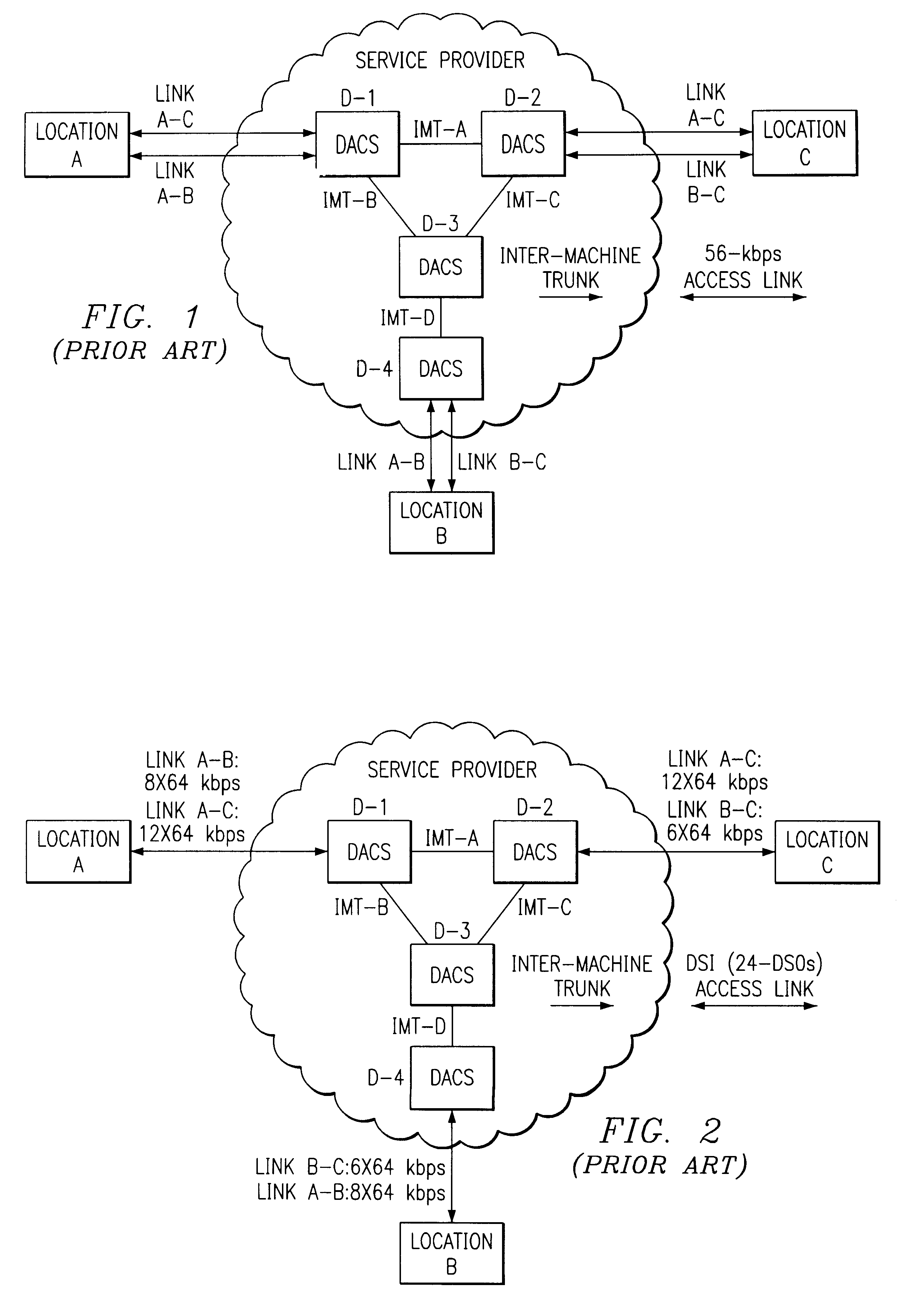
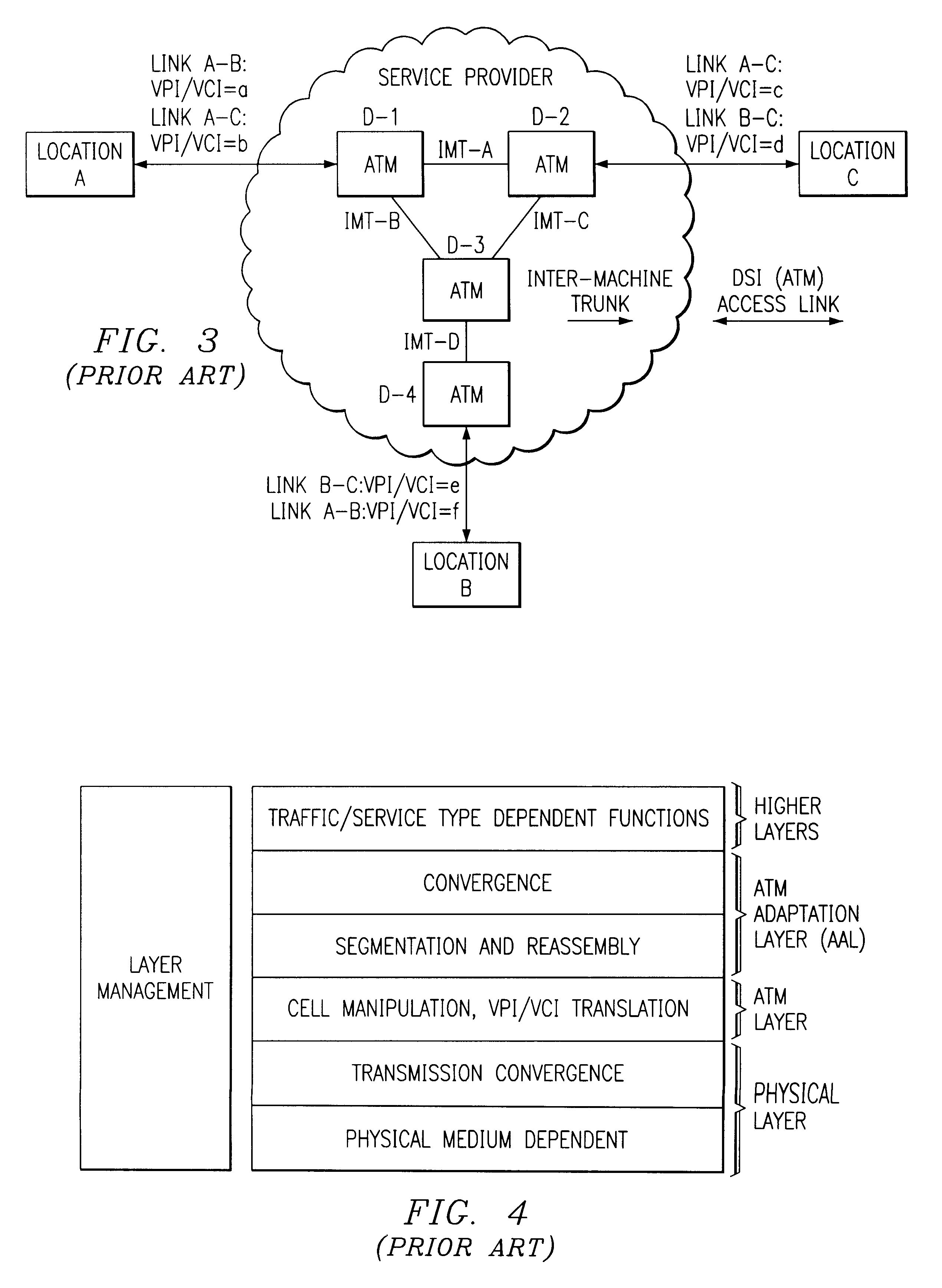
1. Field of the InventionThe invention relates generally to the field of computer networks. More particularly, the invention relates to private computer networks based on asymmetric transfer mode technology. Specifically, a preferred implementation of the invention relates to multi-link segmentation and reassembly for bonding multiple permanent virtual circuits in an inverse multiplexing arrangement.2. Discussion of the Related ArtAsymmetric Transfer Mode (ATM) is a popular technology for providing secure and reliable Virtual Private Network arrangements. The use of ATM Switches permits the Service Provider (such as an Inter-Exchange Carrier, or "IXC") to better utilize the inter-machine trunking facilities by providing trunk bandwidth only when there are ATM cells available for transmission. This is in contrast with the notion of a (truly) Private Network wherein the Service Provider is required to dedicate the prescribed bandwidth for the end customer in all inter-machine trunking...

Claims


Application Information

Patent Timeline
Patent Type & Authority Patents(United States)
IPC IPC(8): H04L12/56H04Q11/04
CPCH04L45/10H04L45/24H04L47/10H04L47/125H04L47/16H04L47/30H04Q11/0478H04L2012/5649H04L2012/565H04L2012/5653H04L2012/5672H04L47/43
Inventor SHENOI, KISHANJACOBSEN, GARYKRABA, KAMILALAI, CHIEN-CHOUSOMMER, JEREMYYANG, JINING
Owner ATWATER PARTNERS LLC OF TEXAS
Learn More