Separator of Fuel Cell

a fuel cell and separator technology, applied in the field of separators of fuel cells, can solve problems such as differential pressure (pressure loss) especially around boundary portions, and achieve the effect of convenient securemen

Inactive Publication Date: 2009-07-02
TOYOTA JIDOSHA KK
View PDF4 Cites 45 Cited by
  • Summary
  • Abstract
  • Description
  • Claims
  • Application Information

AI Technical Summary

Benefits of technology

[0010]The separator having the above-mentioned structure has a structure in which the terminal end position of the convex portion (e.g., a convex rib) is different from that of the concave portion (e.g., a concave groove), in other words, a structure in which a so-called phase of a start end (or a dead end) of the convex portion is different from that of the start end of the concave portion. In this case, an area of an introducing portion, to a gas channel, of the reactant gas flowing, for example, from the distribution channel to the gas channel (or an area of the introducing portion, to a cooling water channel, of the cooling water flowing from the distribution channel to the cooling water channel) can be enlarged. Therefore, as compared with a case where the terminal ends of the convex and concave portions constituting the fluid channel are disposed on the same line without any phase difference as in the conventional example, the differential pressure in the boundary portion between the fluid channel and the distribution channel (the differential pressure which is exerted on the fluid, also referred to as a pressure loss) can be reduced. Therefore, the seal property of the fluid in the fluid channel is easily secured, and the supply pressure (the supply capability) of the reactant gas or the cooling water does not have to be increased as in a conventional structure.

Problems solved by technology

However, in a separator having such a structure, there is a problem that a differential pressure (a pressure loss) especially around a boundary portion between a fluid channel and a distribution channel is large.
When the differential pressure around the boundary portion is thus large, problems might be caused with regard to ease of securing a seal property of a fluid and a magnitude of a gas supply pressure (a supply capability).

Method used


Image

  • Separator of Fuel Cell
  • Separator of Fuel Cell
  • Separator of Fuel Cell

Examples


first embodiment

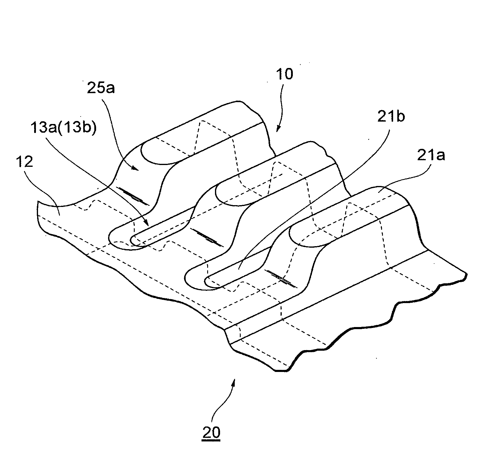
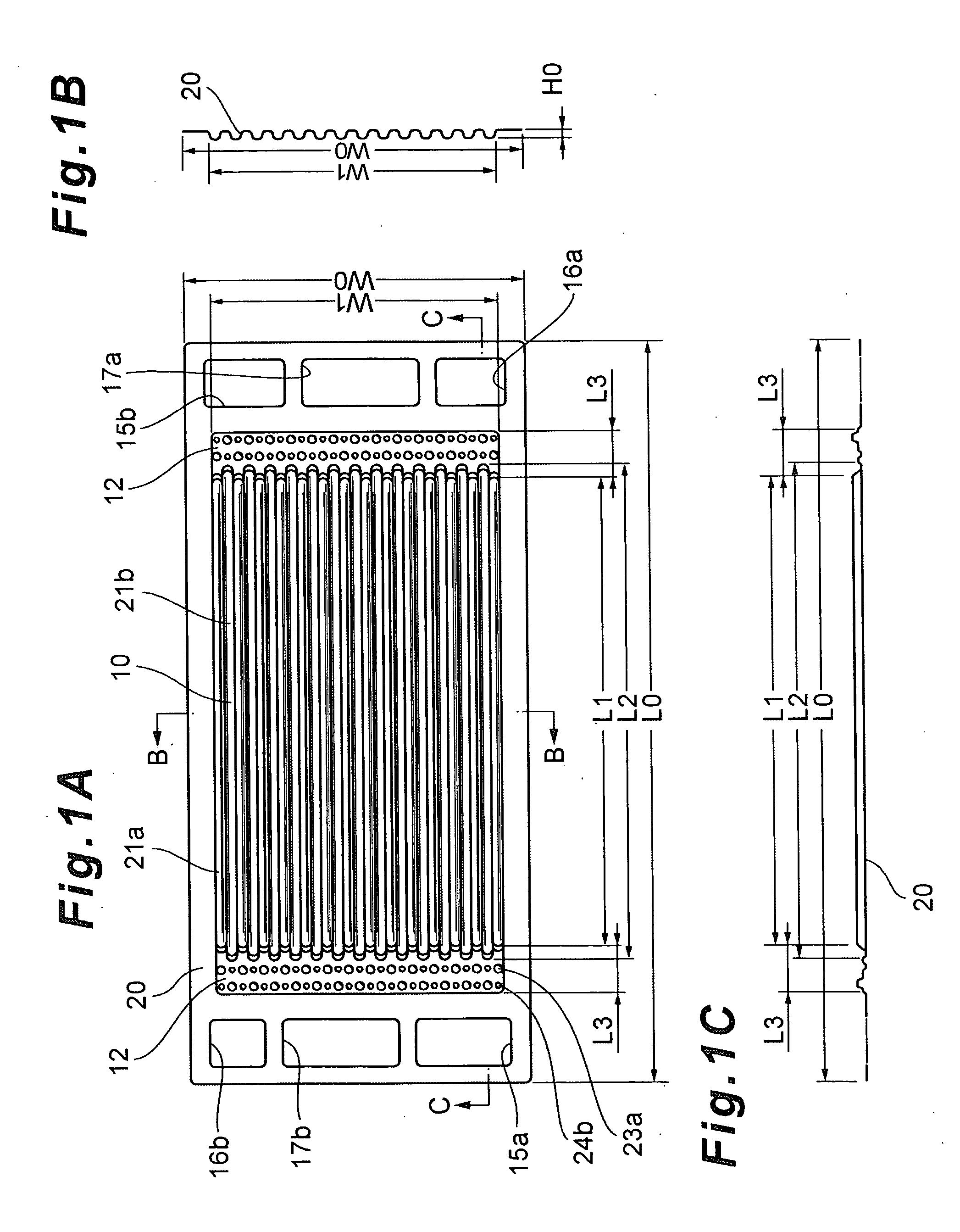
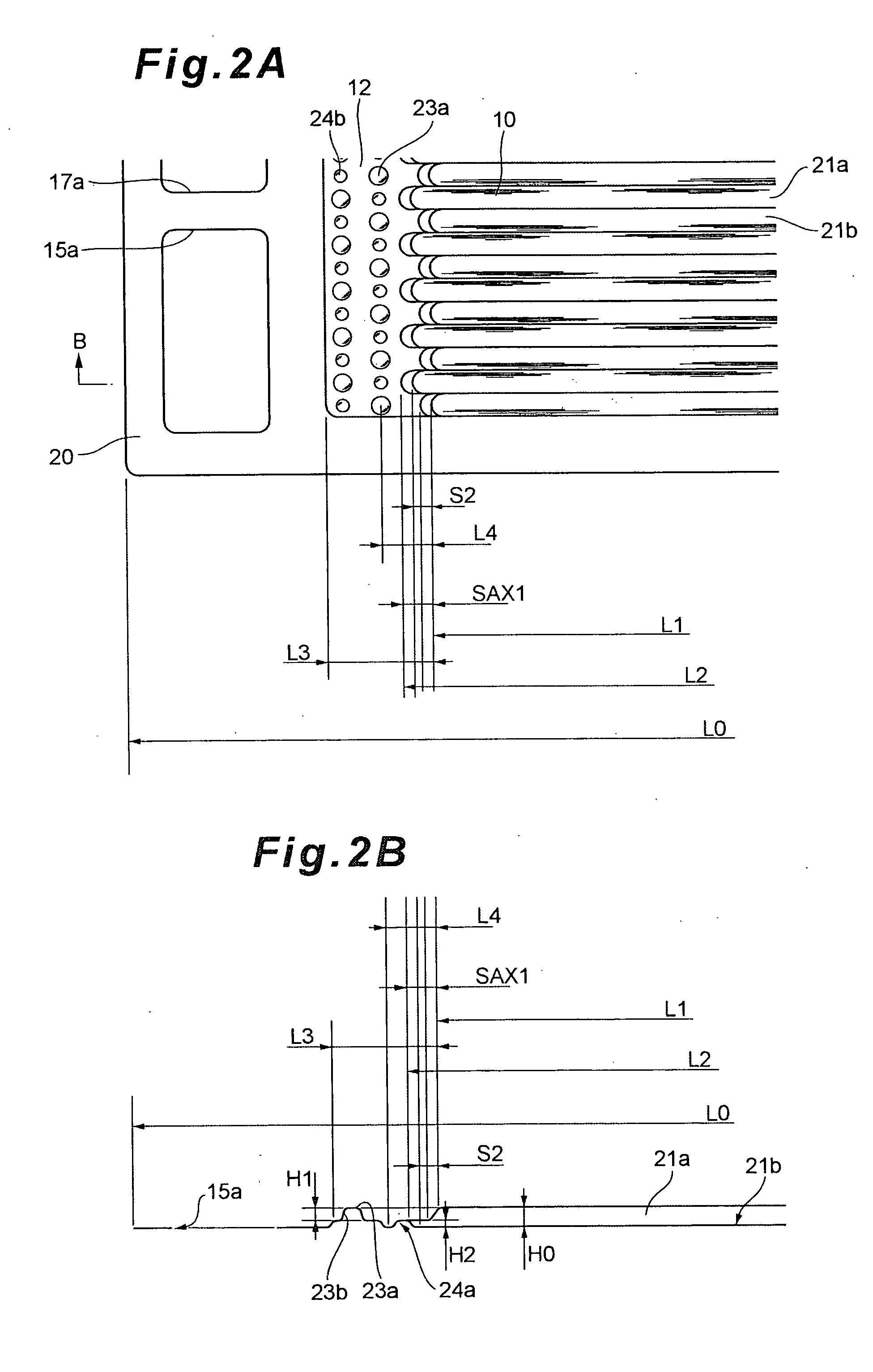
[0050]First, FIG. 1A to FIG. 1C show a separator 20 provided with a straight type gas channel 10. As described above, ends of this separator 20 are provided with inlet manifolds 15a, 16a and 17a and outlet manifolds 15b, 16b and 17b of various fluids (an oxidizing gas, a fuel gas and cooling water). Moreover, both ends of the gas channel 10 are provided with distribution channels 12 for distributing a gas to the gas channels 10 (see FIG. 1A, FIG. 2A, etc.). It is to be noted that a portion where the gas discharged from the gas channel 10 joins will also be referred to as the distribution channel 12 in the present embodiment. That is, in this case, the distribution channel 12 does not substantially distribute the gas, but has a symmetric structure, and the gas can be supplied in either direction. Therefore, in the present embodiment, both the portions are referred to as the “distribution channels” for the sake of convenience.

[0051]This distribution channel 12 is provided with a plura...

second embodiment

[0062]FIG. 5A to FIG. 5C show one example of a structure for reducing a differential pressure in a case where cooling water is introduced from a distribution channel 12 to a linear channel. Contrary to the separator shown in FIG. 3A and the like, this separator 20 satisfies a relation L1>L2. That is, a total length L2 of a concave groove 21b is shorter than a total length L1 of a convex rib 21a, and a terminal end of the convex rib 21a is positioned closer to the distribution channel 12 than a terminal end of the concave groove 21b (see FIG. 5A to FIG. 5C). Here, the convex rib 21a and the concave groove 21b are formed symmetrically with respect to center lines, respectively, and hence eventually, the convex rib 21a in one end of the separator 20 of the present embodiment is formed to be longer than the concave groove 21b as much as SBX1=(L1−L2) / 2 (see FIG. 5A, etc.).

[0063]Moreover, a structure around the terminals of the convex rib 21a and the concave groove 21b in the present embo...

third embodiment

[0069]Next, a case where the present invention is applied to a separator 20 having serpentine type channels will be described (see FIG. 6, FIG. 7).

[0070]FIG. 6 and FIG. 7 show one example of the serpentine type separator 20 viewed from the side of a gas (an oxidizing gas or a fuel gas) channel 10. Ends of this separator 20 are provided with inlet manifolds 15a, 16a and 17a and outlet manifolds 15b, 16b and 17b of various fluids (the oxidizing gas, the fuel gas and cooling water) in the same manner as in the above embodiments (see FIG. 6). In the separator 20 of the present embodiment, distribution channels 12 of the gases are provided in the vicinities of the inlet manifolds 15a, 16a and 17a and the outlet manifolds 15b, 16b and 17b of various fluids (the oxidizing gas, the fuel gas and the cooling water), respectively, and a plurality of straight gas channels 10 (and cooling water channels 36) constituted of a plurality of parallel convex ribs 21a and concave grooves 21b are provid...


PUM

PropertyMeasurementUnit
areaaaaaaaaaaa
total lengthaaaaaaaaaa
height H1aaaaaaaaaa

Abstract

A differential pressure in a boundary portion between a streaked or linear fluid channel formed of a plurality of convex and concave portions disposed adjacent to one another in an undulated manner and a distribution channel for distributing a reactant gas or cooling water to be introduced into the plurality of fluid channels is reduced. In a structure of a separator of a fuel cell having a structure including streaked fluid channels formed of adjacent convex and concave portions formed on the surface of the separator, and a distribution channel which distributes, to these fluid channels, a fluid to be introduced into the fluid channels, in a boundary portion between the linear fluid channel and the distribution channel, a position of a terminal end of the convex portion constituting the fluid channel and a position of a terminal end of the concave portion are displaced in a streak direction of the fluid channel. It is preferable that the terminal end of the concave portion is positioned closer to the distribution channel than the terminal end of the convex portion. It is also preferable that the separator has a structure of such a type that front and back surfaces are integrated.

Description

BACKGROUND OF THE INVENTION[0001]1. Field of the Invention[0002]The present invention relates to a separator of a fuel cell. More particularly, the present invention relates to a structure of a separator for holding an MEA in which electrodes are provided on opposite sides of an electrolyte.[0003]2. Description of Related Art[0004]As a separator to be applied to a fuel cell, there is known a structure provided with streaked or linear fluid channels formed of a plurality of convex and concave portions arranged adjacent to one another in an undulated form, and a distribution channel for distributing a reactant gas or cooling water to be introduced into these fluid channels (e.g., see Patent Document 1).[0005][Patent Document 1] Japanese Patent Application Laid-Open No. 2005-243651SUMMARY OF THE INVENTION[0006]However, in a separator having such a structure, there is a problem that a differential pressure (a pressure loss) especially around a boundary portion between a fluid channel an...

Claims


Application Information

Patent Timeline
Patent Type & Authority Applications(United States)
IPC IPC(8): H01M2/02
CPCH01M8/0206H01M8/0254H01M8/026Y02T90/32H01M2008/1095H01M2250/20Y02E60/50H01M8/0267H01M8/0258H01M8/0263H01M8/2483Y02T90/40H01M8/0265H01M8/0273
Inventor IKEDA, SADAO
Owner TOYOTA JIDOSHA KK
Why Eureka
Try Eureka