
System and method for location area planning in mobile communication networks under delay bound

a technology of mobile communication network and location area, applied in the direction of network data management, wireless communication, electrical equipment, etc., can solve the problems of limited wireless bandwidth, limited amount of wireless bandwidth, and a large amount of control messages that require significant amounts of wireless bandwidth,

Active Publication Date: 2009-07-02
VERIZON PATENT & LICENSING INC
View PDF4 Cites 9 Cited by
  • Summary
  • Abstract
  • Description
  • Claims
  • Application Information

AI Technical Summary

Benefits of technology

The patent text describes a system and method for reducing paging costs in mobile communication networks. The system uses probability-based approaches to prioritize cells or groups of cells that are more likely to contain a mobile terminal and minimize the number of paging operations. The system can adapt to different network architectures, location distribution patterns, and network applications to effectively locate mobile terminals while remaining within a predetermined delay bound. The technical effect of the patent text is to provide a paging approach that reduces paging costs for a wide variety of mobile communication networks.

Problems solved by technology

In many such networks, both communication traffic and control messages share a limited amount of wireless bandwidth.
Unfortunately, control messages often require significant amounts of wireless bandwidth to ensure proper operation of the network.
Unfortunately, conventional registration and paging operations often impose a significant load on wireless bandwidth resources, especially during times of high call volume or when networks provide service to significant numbers of mobile terminals.
Both registration and paging operations impose costs on mobile communication networks, namely by reducing the overall available wireless bandwidth.
However, registration costs will be at a maximum as wireless terminals register their new locations at every instance of moving from one cell to another.

Method used


Image

  • System and method for location area planning in mobile communication networks under delay bound
  • System and method for location area planning in mobile communication networks under delay bound
  • System and method for location area planning in mobile communication networks under delay bound

Examples


Embodiment Construction

I. Overview

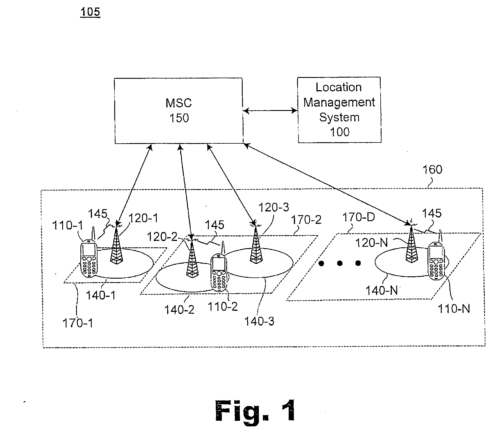
[0029]A system and method for locating mobile terminals in mobile communication networks under delay bound is disclosed. More specifically, the system and method (collectively the “system”) provide a process of forming and polling paging areas in a manner that generally reduces average paging costs while keeping delays within a predetermined bound. Paging cost refers to the average amount of wireless bandwidth used for paging operations, which is directly related to the number of cells the network has to page in order to locate a mobile terminal.

[0030]As discussed below in greater detail, a threshold may be set based on both location probabilities of cells within a location area and a predetermined delay bound. Location probabilities refer to quantified probabilities of a mobile terminal (e.g., a cellular telephone) being at a particular location (e.g., within a particular cell) within a location area of a mobile communication network. Delay bound refers to a predetermine...


PUM


Abstract

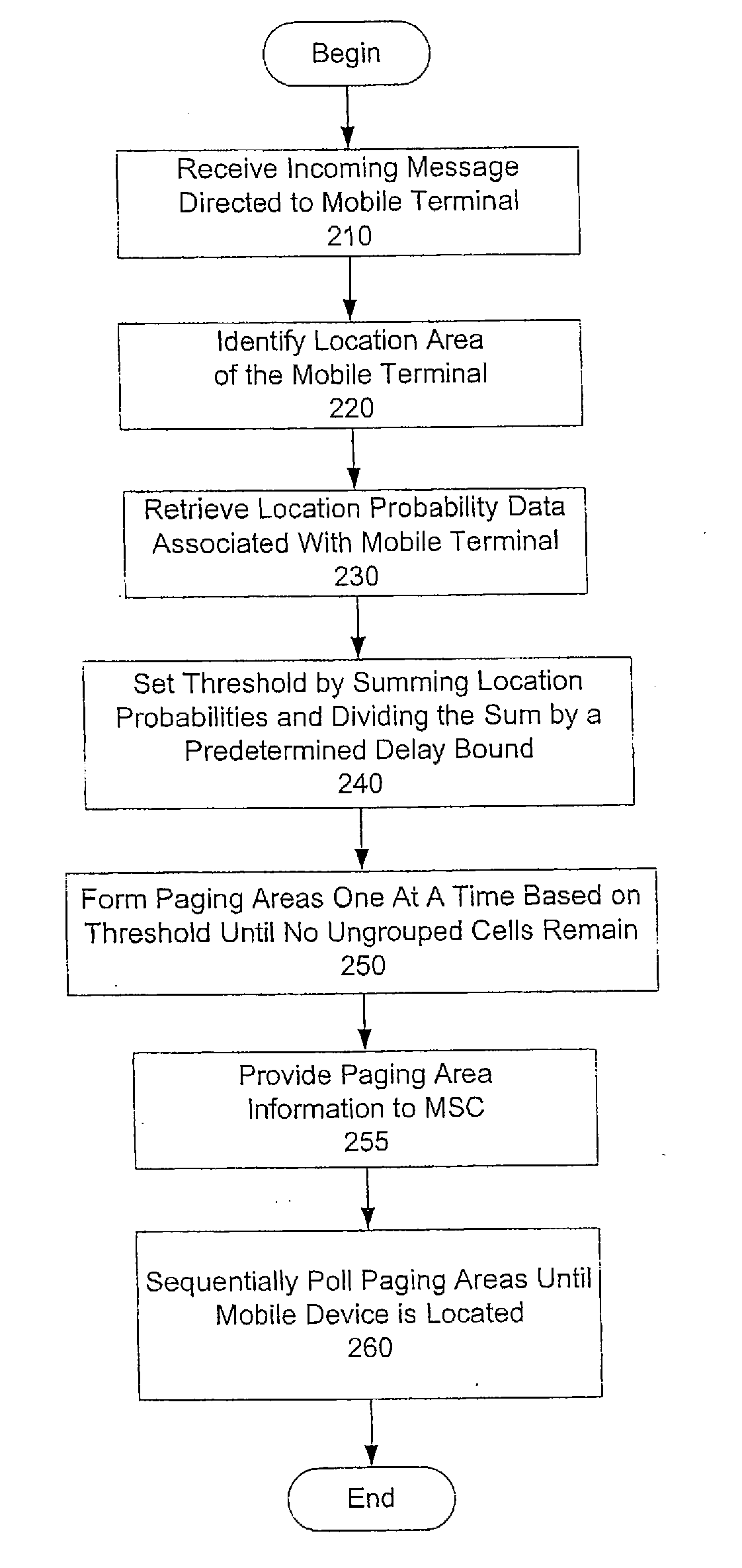
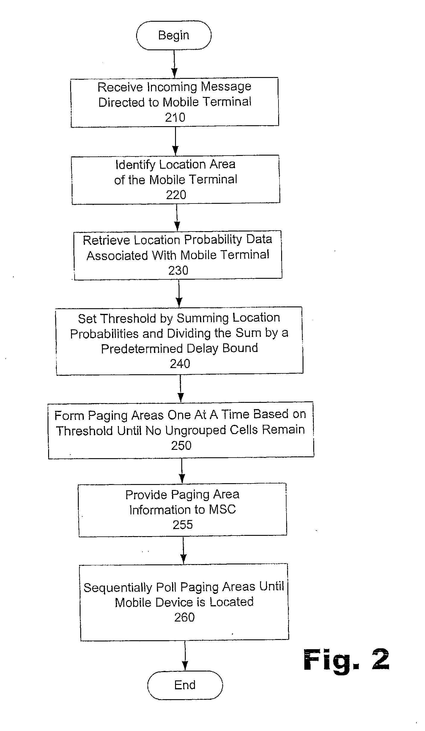
In one of many possible embodiments, a method of locating a mobile terminal within a location area of a mobile communication network is provided. In the method, a threshold is set by calculating a sum of all location probabilities in the location area and dividing the sum by a maximum number of polling cycles allowed before the mobile terminal is located. Cells in the location area are arranged in non-ascending order according to their location probabilities. Multiple paging areas are formed one at a time by starting with a first cell not used in a previous paging area, grouping cells in order, and stopping when the total of location probabilities reaches the threshold or when no more ungrouped cells exist within the location area.

Description

RELATED APPLICATIONS[0001]This application claims priority under 35 U.S.C. §119(e) to U.S. Provisional Patent Application Ser. No. 60 / 618,884, by Hui Liu, filed on Oct. 14, 2004, and entitled A SYSTEM AND METHOD FOR LOCATION AREA PLANNING 1N MOBILE COMMUNICATION NETWORKS UNDER DELAY BOUND, the contents of which are hereby incorporated by reference in their entirety.BACKGROUND INFORMATION[0002]Wireless bandwidth is one of the most valuable resources in mobile communication networks. In many such networks, both communication traffic and control messages share a limited amount of wireless bandwidth. Unfortunately, control messages often require significant amounts of wireless bandwidth to ensure proper operation of the network. For example, to effectively provide communication services to mobile terminals, mobile communication networks typically use control messages to track and manage the locations of the terminals within the networks.[0003]A typical mobile communication network (e.g....

Claims


Application Information

Patent Timeline
Patent Type & Authority Applications(United States)
IPC IPC(8): H04W24/00
CPCH04W68/08H04W8/02
Inventor LIU, HUI
Owner VERIZON PATENT & LICENSING INC
Learn More