Method for Manufacturing a Bearing Shell Assembly, and Bearing Shell Assembly for a Ball Joint
- Summary
- Abstract
- Description
- Claims
- Application Information
AI Technical Summary
Benefits of technology
Problems solved by technology
Method used
Image

Examples
Embodiment Construction
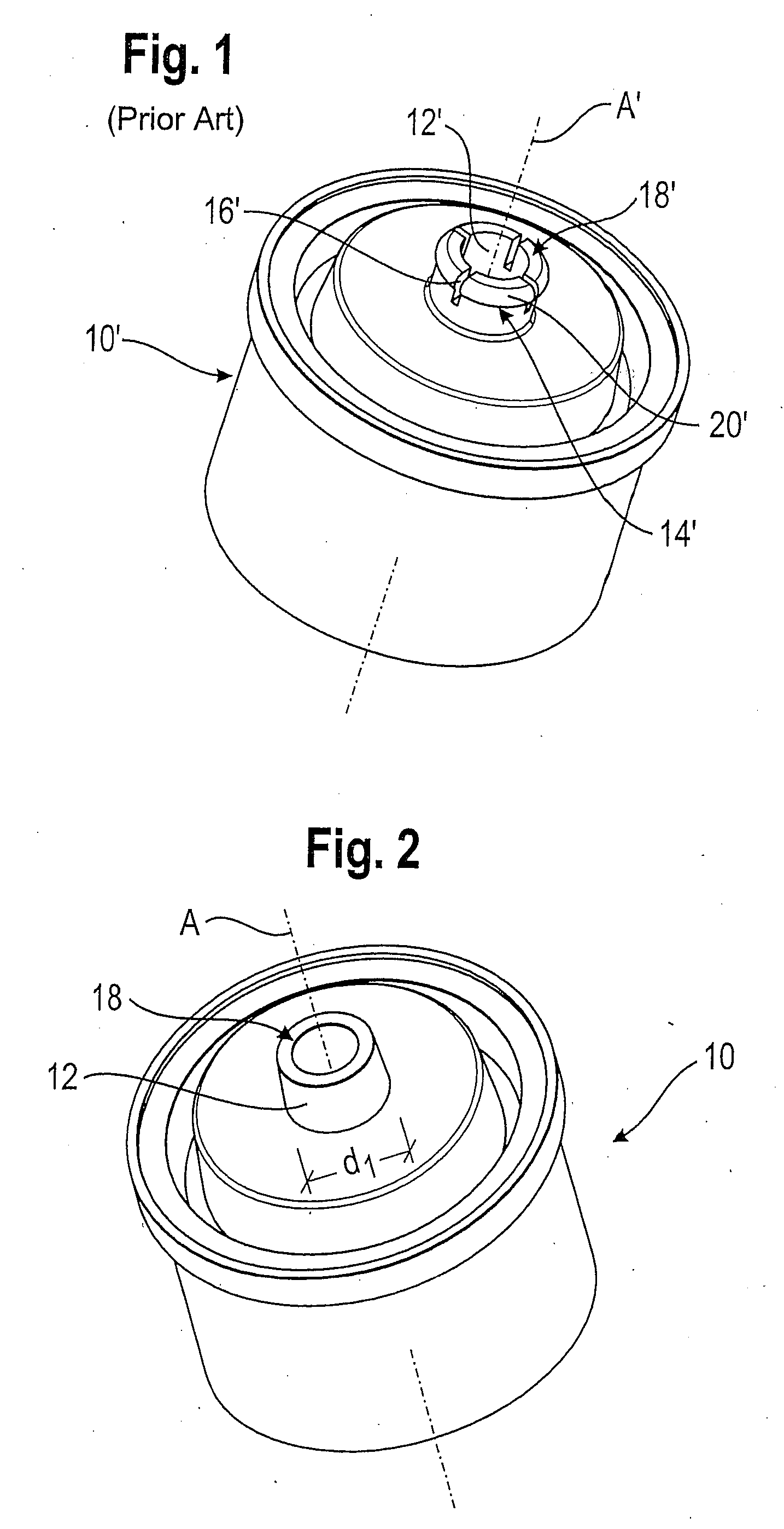
[0028]FIG. 1 shows a known bearing shell 10′ for a ball joint, with a shape which is substantially rotationally symmetrical to a longitudinal axis A′. The bearing shell 10′ has an axial extension 12′, on which latching elements 14′ are formed. The latching elements 14′ can enter into a snap-on connection with a spring element (not shown) in order to fasten the spring element to the bearing shell 10′, so that a pre-mounted bearing shell assembly is produced. According to FIG. 1, the axial extension 12′ is subdivided by notches 16′ into four radially movable latching elements 14′. At a free, axial end 18′ of the extension 12′, each latching element 14′ has a formed-on build-up or undercut, which respectively forms a detent nose 20′ of the associated latching element 14′.
[0029]If a spring element, such as for example a plate spring with a suitable opening, is pressed in the axial direction onto the extension 12′, then the latching elements 14′ deform radially inwards until the plate sp...
PUM
| Property | Measurement | Unit |
|---|---|---|
| Diameter | aaaaa | aaaaa |
| Plasticity | aaaaa | aaaaa |
| Deformation enthalpy | aaaaa | aaaaa |
Abstract
Description
Claims
Application Information