Gravity slide ride system

a gravity slide and ride technology, applied in amusements, entertainment, roundabouts, etc., can solve the problems of passive or non-powered/non-actuated vehicle movement on the track

Active Publication Date: 2012-04-12
DISNEY ENTERPRISES INC
View PDF1 Cites 0 Cited by
  • Summary
  • Abstract
  • Description
  • Claims
  • Application Information

AI Technical Summary

Benefits of technology

[0008]The “gravity slide” ride described herein provides a number of advantages over conventional round rides. The radial sliding provides a new ride experience. The ride provides an unusual vehicle motion with minimal rigid attachment to structure and provides for large variation in lateral or radial position. Passengers experience increased speed as their vehicle moves outward along the track. The gravity slide ride is not complex to manufacture, install, maintain, or control and is likely relatively inexpensive to provide as a new park ride. The drive system spins the central structure or hub as well as the tracks that extend radially outward from the hub. However, the motion of the vehicles on the track is passive or non-powered / non-actuated as they simply slide in response to centrifugal forces. Hence, the ride has a single actuator / motor system, and all motion / dynamics come from rotation of the hub and, hence, vehicle motion / dynamics may be varied simply by changing the rotational speeds of the hub. The track geometry or shape may be customized or designed to provide a wide variety of radial / lateral vehicle travel paths, e.g., a track with an axial twist along its length can rotate the vehicle relative to the ground as it moves radially inward and outward on the travel path defined by the track.
[0011]In one embodiment of the ride, the mounting assembly rollably engages the track such that the passenger vehicle rolls on the track between the first and second positions as the drive increases or decreases the rotation rate of the hub between the first and second rotation rates. For example, a bogie or wheel carrier may engage outer surfaces of the track body or an inner channel of the track body. The mounting assembly may couple or connect with the track to position the passenger vehicle between the track and the foundation (or to position the vehicle above or along one side of the track body). The ride may support interactivity such as by having the passenger vehicle include an input device operable by a passenger of the passenger vehicle to limit a rate of movement of the passenger vehicle between the first and second positions (e.g., a braking system), whereby the input device is operable to define a radial position of the passenger vehicle relative to the axis of rotation.

Problems solved by technology

However, the motion of the vehicles on the track is passive or non-powered / non-actuated as they simply slide in response to centrifugal forces.

Method used


Image

  • Gravity slide ride system
  • Gravity slide ride system
  • Gravity slide ride system

Examples


Embodiment Construction

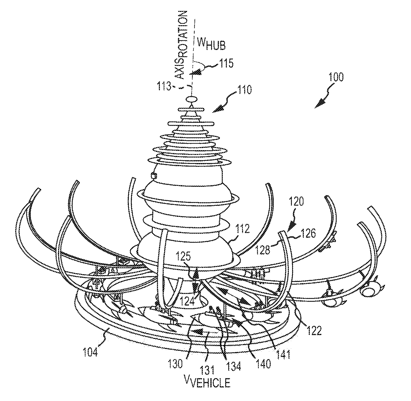
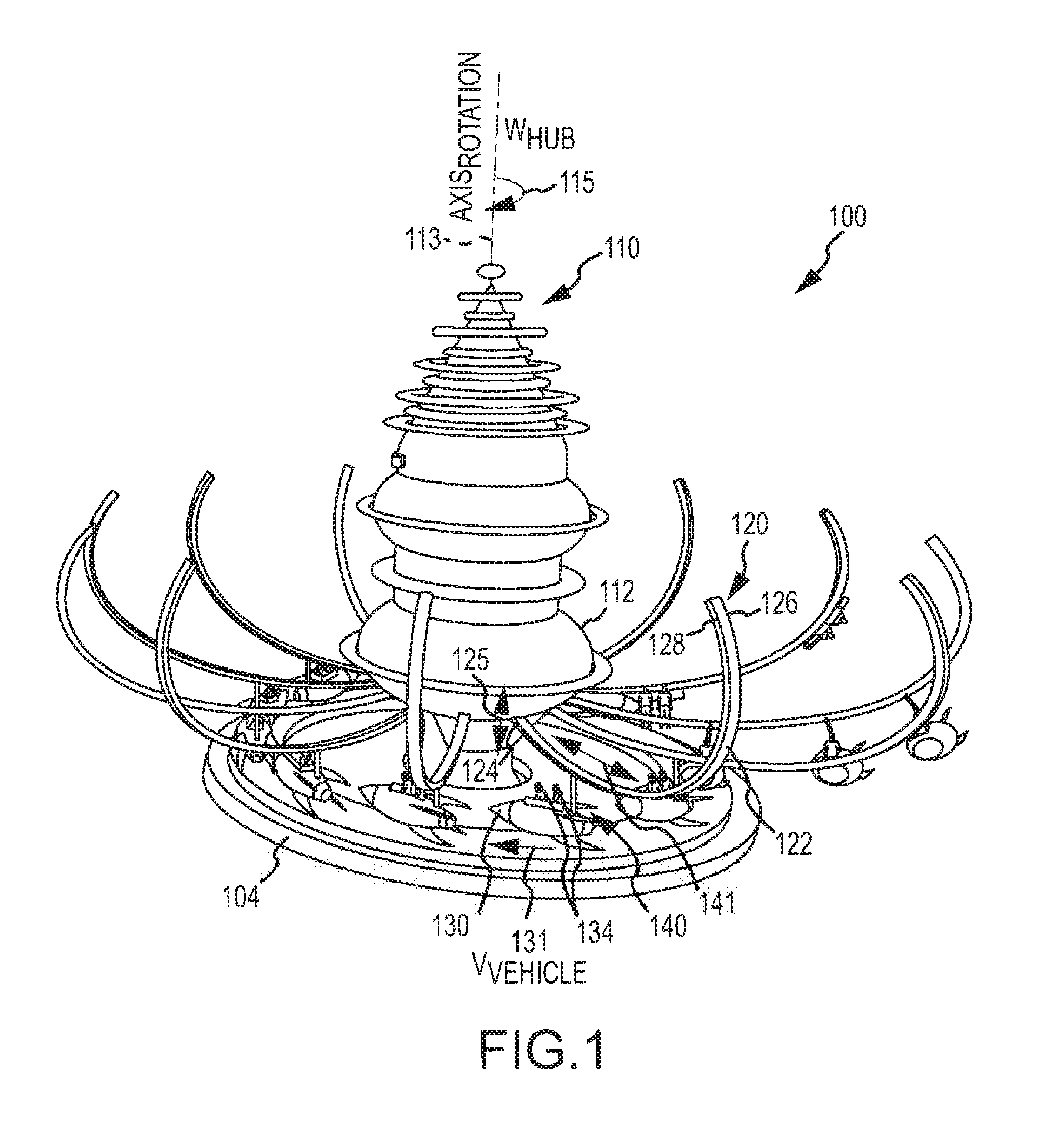
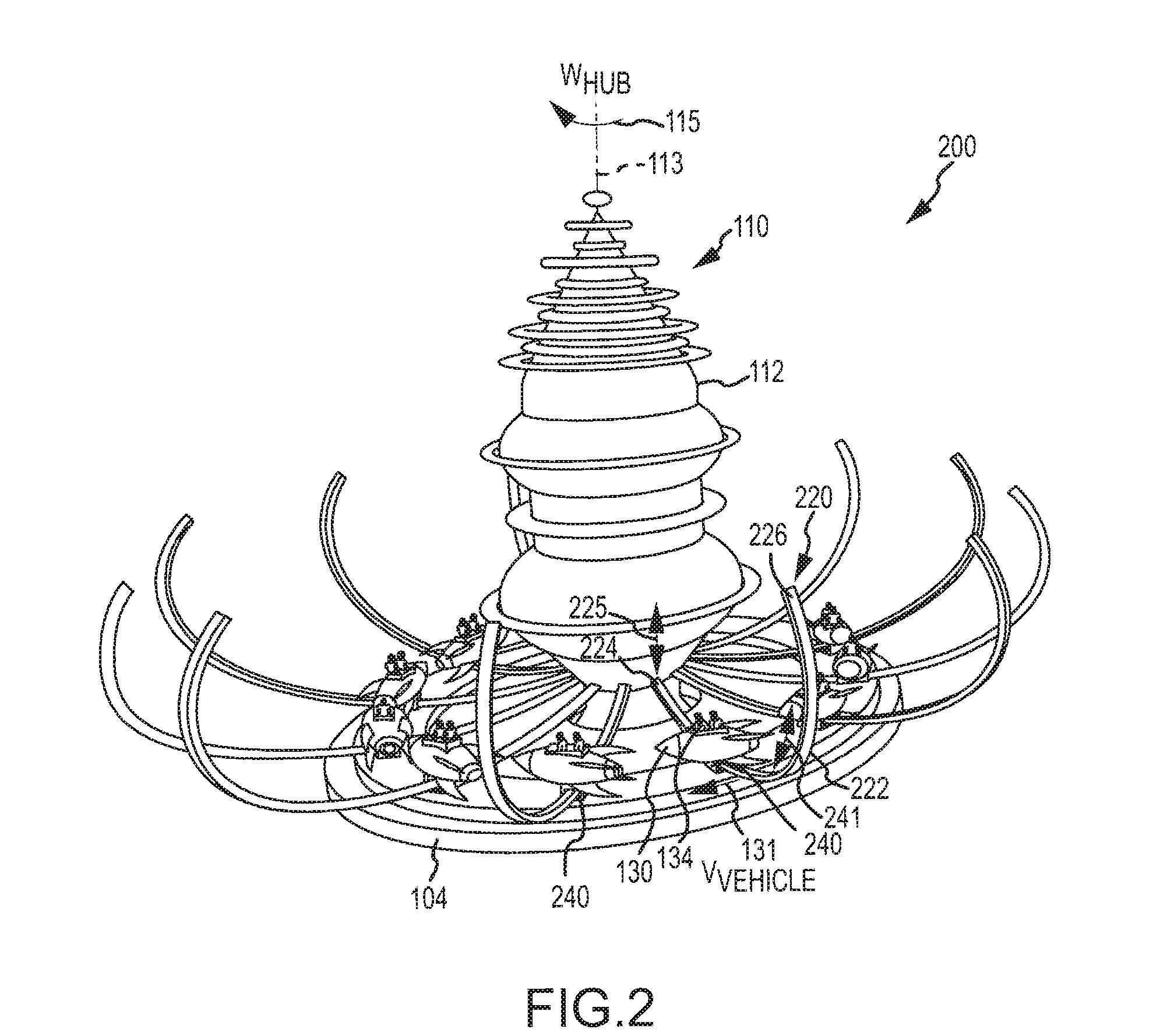
[0023]The description is generally directed to an amusement park ride that provides a fun and exciting ride experience utilizing a simple rotating structure (e.g., a rotating central hub). A gravity-based slide ride system is provided with a central rotatable structure or hub and multiple tracks or support arms that include track elements with two or more slopes of increasing magnitude as the outer end or tip of the track element is approached. The tracks are attached at a first end to the hub via a rigid coupling or via a connection that may be pivoted by a ride control system based on a ride program or in response to input from a passenger in a vehicle (e.g., operate a joystick to cause the track to pivot up or down). The tracks extend radially outward from the hub to a second end. A passenger-carrying vehicle is attached to each track with a vehicle-to-track mounting assembly. Significantly, the mounting assembly is configured such that the vehicle is attached to the track in a m...


PUM


Abstract

A rotating hub ride configured to position passenger vehicles at different vehicle radii relative to the hub's axis of rotation. The ride includes curved support arms extending outward from the hub, with a first end coupled to the hub at a lower height than a second end of the arm. A vehicle is attached, via a mounting assembly, to each curved support arm to slide radially inward and outward on the arm in response to forces applied to the vehicle due to rotation of the hub, e.g., at two or more hub rotation rates. The arm or track defines a travel path for radial movement of the vehicle. When hub rotation is halted, the vehicle slides inward on the track to a load position corresponding to a minimum vehicle radius. At increasing hub speeds, the vehicle slides outward to position the vehicle in any of a number of vehicle radii.

Description

BACKGROUND[0001]1. Field of the Description[0002]The present description relates, in general, to amusement park rides and other entertainment rides such as round rides, and, more particularly, to amusement or theme park round rides configured to position vehicles at two or more radii on support arms that are attached to a central hub. The central hub is rotated at two or more speeds so as to provide passengers in the vehicles a dynamically changing ride experience.[0003]2. Relevant Background[0004]Amusement and theme parks are popular worldwide with hundreds of millions of people visiting the parks each year. Park operators continuously seek new designs for rides that attract and continue to entertain park visitors. Many parks include round rides that include vehicles or gondolas mounted on support arms extending outward from a centrally located structure that is rotated by a drive assembly. The passengers or riders sit in the vehicles and are rotated by the drive assembly, which sp...

Claims


Application Information

Patent Timeline
Patent Type & Authority Applications(United States)
IPC IPC(8): A63G1/28
CPCA63G1/48A63G1/10A63G1/08
Inventor CRAWFORD, DAVID W.NEMETH, EDWARD A.
Owner DISNEY ENTERPRISES INC
Why Eureka
Try Eureka