Coded Aviation Snips

a technology for aviation snips and color codes, applied in the field of aviation snips, can solve the problems of not being able to rely on the color coding system, preventing users from determining the cutting direction, and not being able to recognize the colors applied to the snip handl

Inactive Publication Date: 2009-07-09
BLACK & DECKER INC
View PDF5 Cites 13 Cited by
  • Summary
  • Abstract
  • Description
  • Claims
  • Application Information

AI Technical Summary

Benefits of technology

[0016]One advantage of the coded aviation snips of the invention is that the visible graphic indicia identifies the respective type of snip, and not just the cutting direction of the snip as with the color coding scheme of the prior art. Yet another advantage of the coded aviation snips of the invention is that it need not be color dependent, and therefore is effective for users with color blindness or other visual irregularities that prevent reliance on the color coding scheme of the prior art. Another advantage of some currently preferred embodiments of the invention is that the user can both visually and non-visually (i.e. by feel) determine the cutting direction (i.e. straight, left, right) of a particular type of snip. Additionally, in some such embodiments, the user can both visually and non-visually (i.e. by feel) determine the exact type of snip of a set of aviation snips (i.e. straight cutting, bulldog, left cutting, right cutting, offset left cutting, and offset right cutting). Furthermore, in some such embodiments, the user can both visually and non-visually (i.e. by feel) determine the correct orientation of the snip during use.

Problems solved by technology

One drawback is that the color coding is only applied to the handle of the snip, which prevents users from determining the cutting direction of a particular snip if the handle is covered or otherwise not in the user's line of sight.
Another drawback to the color coding system recited above is that the system typically is the sole system used to assist users in identifying the cutting direction of aviation snips.
Therefore, users with color blindness or other visual impairments that make it impossible or difficult to recognize the colors applied to snip handles will not be able to rely on this color coding system to identify the cutting direction of the snips.
Another drawback to the color coding system recited above is that the system provides no indication representative of the specific types of aviation snips (i.e. straight aviation, bulldog aviation, left aviation, right aviation, offset left aviation, offset right aviation, etc.); that is, the system is only capable of indicating cutting direction.
For example, if a user sees a red handled snip in his or her toolbag, he or she will not be able to determine whether the snip is a left cutting snip or an offset left cutting snip, etc.

Method used


Image

  • Coded Aviation Snips
  • Coded Aviation Snips
  • Coded Aviation Snips

Examples


Embodiment Construction

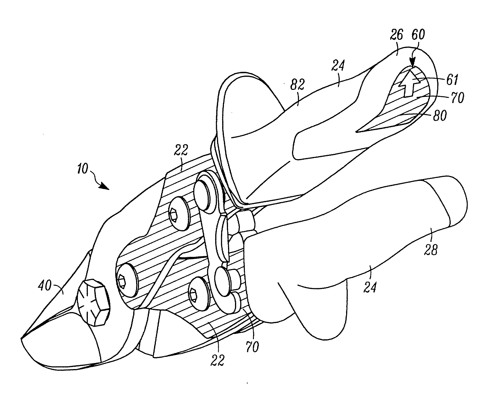
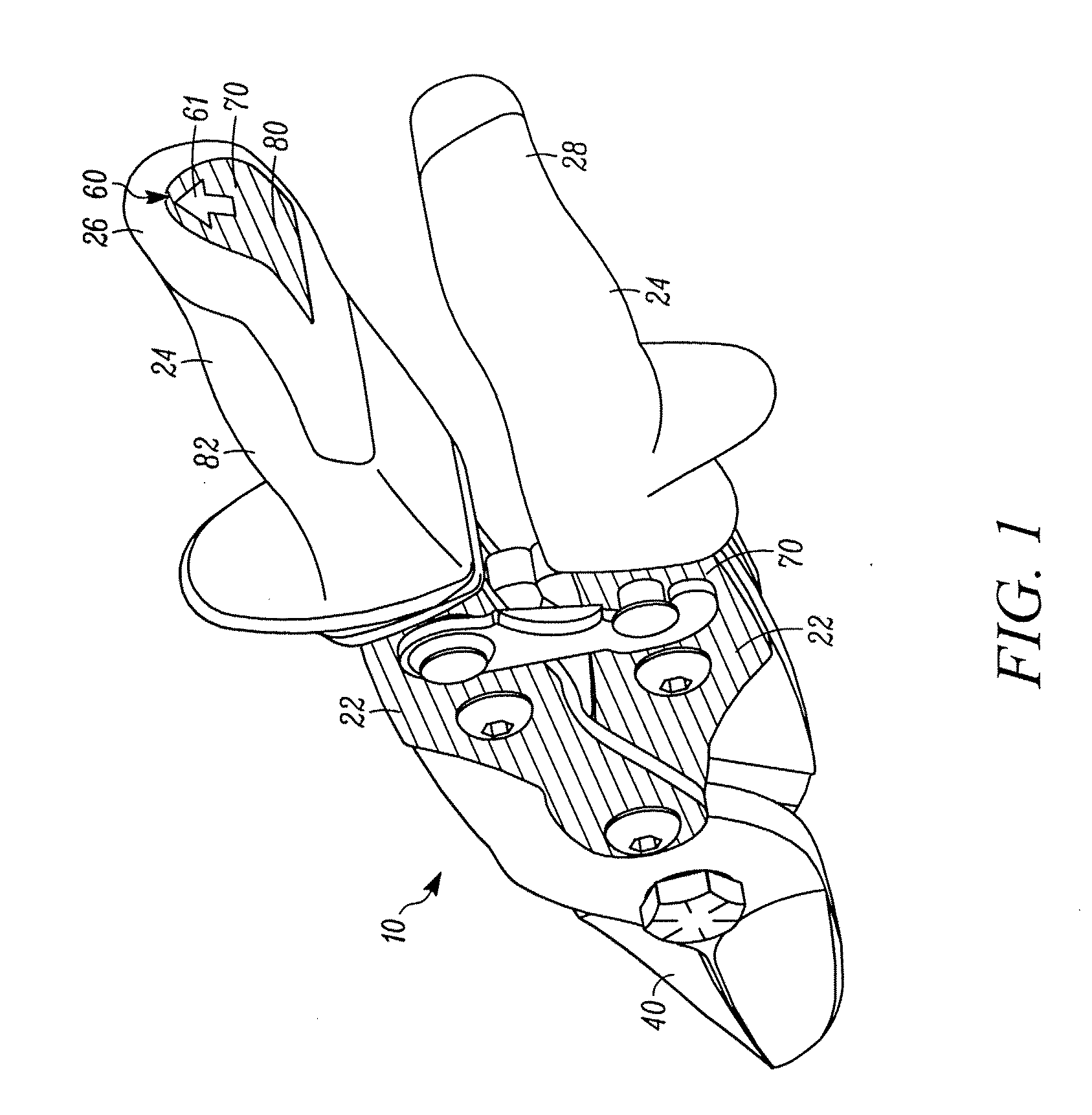
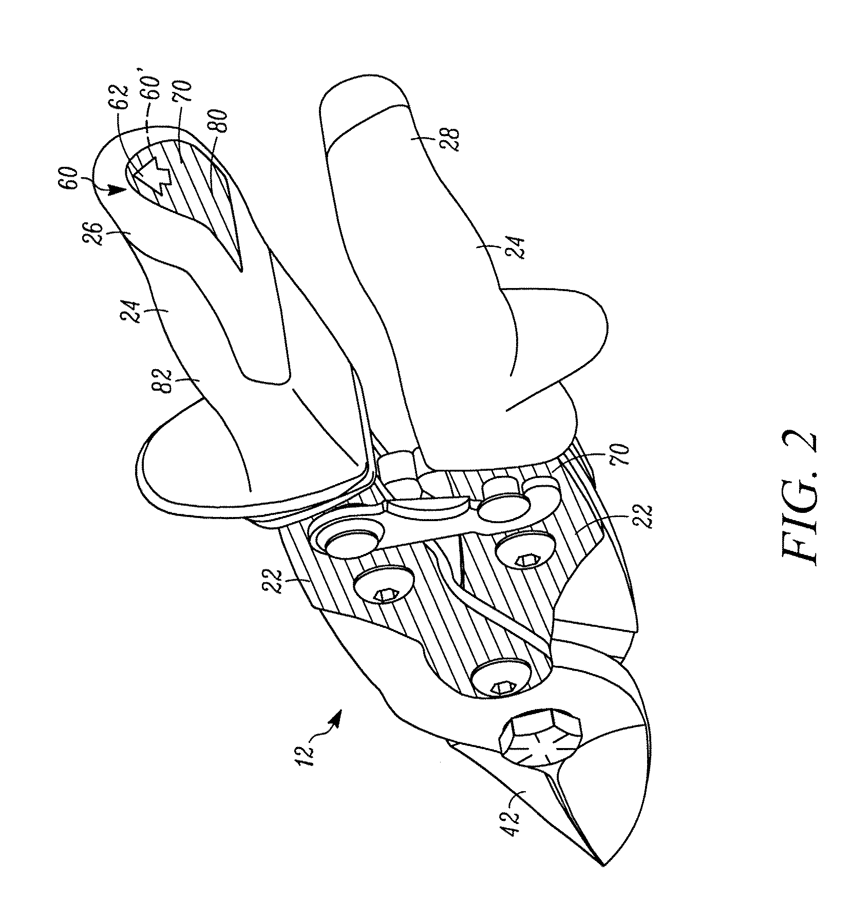
[0026]The invention is directed to a plurality of aviation snips comprising a visual representation indicative of the respective type of snip and visibly different from the visual representation of every other type of snip. In the illustrated embodiments, the plurality of snips includes at least: a straight cutting aviation snip 10 (FIG. 1), a short straight cutting or “bulldog” aviation snip 12 (FIG. 2), a left cutting aviation snip 14 (FIG. 3), a right cutting aviation snip 16 (FIG. 4), an offset left cutting aviation snip 18 (FIG. 5) and an offset right cutting aviation snip 20 (FIG. 6). It should be known, however, that the system is easily expandable to include additional aviation snips and other hand tools.

[0027]Referring to FIGS. 1-6, a typical embodiment of each of the above-mentioned aviation snips is shown. Each snip 10, 12, 14, 16, 18, 20 includes a spine 22 and a handle 24 overlying a portion of the spine 22. The handle 24 comprises an upper grip 26 and a lower grip 28, ...


PUM

PropertyMeasurementUnit
lengthaaaaaaaaaa
curvatureaaaaaaaaaa
color codingaaaaaaaaaa

Abstract

A plurality of aviation snips, each snip comprising a visible graphic indicia indicative of the respective type of snip and visibly different from the graphic indicia of every other type of snip. The indicia is placed on the end portion of the upper handle grip to indicate the orientation of the snip relative to the user's hand during use, and is optionally debossed to add a tactile feel element to the indicia such that the user can determine the type of snip by feeling the indicia without visual contact. Each snip is optionally color coded on the spine of the snip to indicate the cutting direction of the snip.

Description

FIELD OF THE INVENTION[0001]The present invention relates to aviation snips and, more particularly, a set of aviation snips coded to indicate the type and / or cutting direction of each snip.BACKGROUND[0002]Aviation snips are hand tools used to cut sheet metal, linoleum, carpet, tile and other materials. The snips typically employ a compound lever mechanism that reduces the amount of effort required to cut the material in comparison to single lever snips commonly known as tin snips. The most common types of aviation snips are the straight cutting aviation snip, the left cutting aviation snip and the right cutting aviation snip. Additionally, there is a straight short cutting or “bulldog” aviation snip, as well as an offset left cutting aviation snip and an offset right cutting aviation snip. The offset snips maintain the user's hands above the work piece during use.[0003]To assist the end user in determining the cutting direction of a particular snip, manufacturers color the handles a...

Claims


Application Information

Patent Timeline
Patent Type & Authority Applications(United States)
IPC IPC(8): B26B13/00
CPCB26B13/14B23D29/026
Inventor NOVAK, JOSEPH THOMASWEREMCHUK, PETER
Owner BLACK & DECKER INC
Why Eureka
Try Eureka