Imaging device driver and photography instrument employing it

a technology of image pickup device and driver, which is applied in the direction of instruments, printers, camera focusing arrangement, etc., can solve the problems of difficult to reduce the size of the apparatus, large motor, and defocusing of photographs, and achieve the effect of reducing the friction between the movable portion and the image pickup device holding portion, and smooth moving an image pickup devi

Inactive Publication Date: 2009-07-09
PANASONIC CORP
View PDF2 Cites 20 Cited by
  • Summary
  • Abstract
  • Description
  • Claims
  • Application Information

AI Technical Summary

Benefits of technology

[0014]With such a configuration, since three spheres are disposed between the movable portion and the image pickup device holding portion, friction generated between the movable portion and the image pickup device holding portion is reduced. Thus, it is possible to provide an image pickup device driving apparatus capable of smoothly moving an image pickup device in the optical axis direction even with a relatively small driving force.
[0035]As mentioned above, it is possible to provide an image pickup device driving apparatus capable of smoothly moving an image pickup device in the optical axis direction even with a relatively small driving force and a photographing apparatus using the same.

Problems solved by technology

For example, there is a problem that if the optical path length is set to an optimal length with respect to the photographing with visible light in the daytime, a photographed image defocuses when the photographing using visible light and infrared light is performed at night.
Therefore, since it is necessary to provide two axes, the structure becomes larger in the optical axis direction, making it difficult to reduce the size of the apparatus.
However, as mentioned above, since the image pickup device is urged with a large force in the direction of the adjustment ring, in order to rotate the adjustment ring, a large motor is needed.
Therefore, it is difficult to move the image pickup device smoothly by a small motor with a relatively small driving force.

Method used


Image

  • Imaging device driver and photography instrument employing it
  • Imaging device driver and photography instrument employing it
  • Imaging device driver and photography instrument employing it

Examples


Embodiment Construction

[0086]Hereinafter, an exemplary embodiment of the present invention is described with reference to drawings.

Exemplary Embodiment

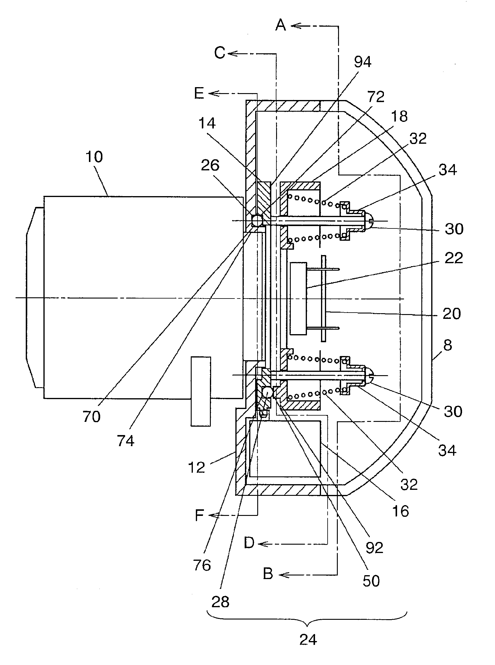
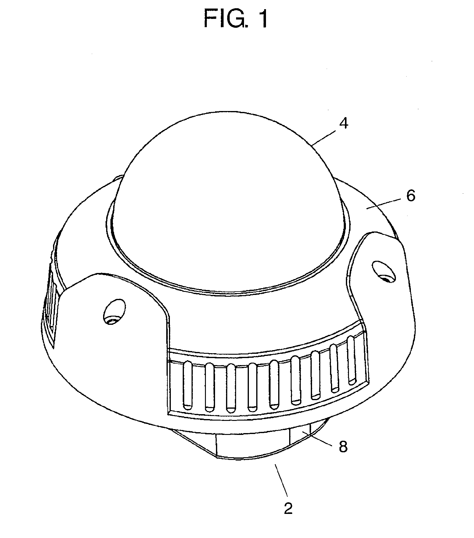
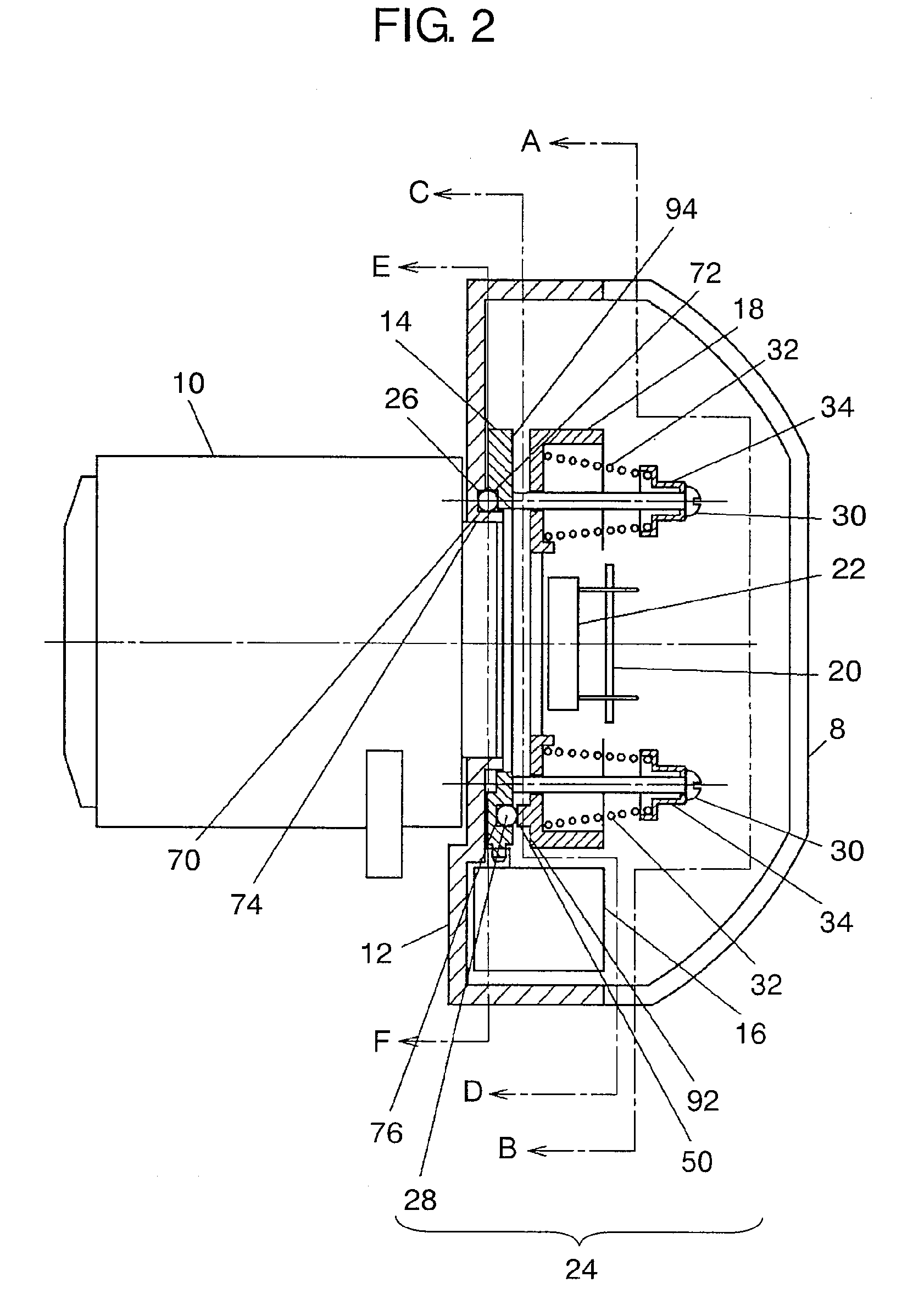
[0087]Firstly, a configuration of photographing apparatus 2 in accordance with an exemplary embodiment of the present invention is described. FIG. 1 is a perspective view showing an outer appearance of photographing apparatus 2 in accordance with an exemplary embodiment of the present invention; and FIG. 2 is a sectional view showing a configuration of image pickup device driving apparatus 24 installed in photographing apparatus 2 in accordance with an exemplary embodiment of the present invention.

[0088]Firstly, as shown in FIG. 1, photographing apparatus 2 includes lens cover portion 4 for preventing damage by shock from the outside and contamination of dusts, and the like, and which is formed of a member having a high transmittance with respect to a ray of light in the wavelength at which photographing is performed; and upper case 6 and lower case 8 provi...


PUM


Abstract

An image pickup device driving apparatus including an image pickup device holding portion for holding an image pickup device with an image pickup surface directed to a predetermined direction and capable of moving in an optical axis direction; a movable portion provided facing the image pickup device holding portion and capable of moving with respect to the image pickup device holding portion; three inclined portions provided on a surface of any one of the movable portion and the image pickup device holding portion, which faces the other; three spheres provided on a surface of the other of the movable portion and the image pickup device holding portion, which faces the three inclined portions, in a way in which they are respectively brought into contact with the three inclined portions; and a driving portion for moving the movable portion so as to change positions in which the three inclined portions and the three spheres are brought into contact with each other and to move the image pickup device held in the image pickup device holding portion in the optical axis direction with the surface direction of the image pickup surface maintained.

Description

TECHNICAL FIELD[0001]The present invention relates to a photographing apparatus such as a monitoring camera apparatus or a video camera apparatus, and more particularly, to an image pickup device driving apparatus for moving an image pickup device in an optical axis direction of a lens and a photographing apparatus using the same.BACKGROUND ART[0002]Firstly, a technology of a conventional photographing apparatus is described. Herein, as an example of a photographing apparatus, a monitoring camera apparatus is described.[0003]Recently, a technology related to various monitoring camera apparatuses has been proposed. In particular, in a monitoring camera apparatus for performing a monitoring operation day and night, a technology of disposing an infrared-light cut filter for selectively transmitting visible light and absorbing infrared light on the front surface of an image pickup device and performing photographing in the daytime, and removing the infrared-light cut filter disposed on ...

Claims


Application Information

Patent Timeline
Patent Type & Authority Applications(United States)
IPC IPC(8): H04N5/228H04N5/225H04N7/18
CPCG02B7/04H04N5/2251G03B3/00H04N23/50
Inventor UCHIDA, TAMOTSU
Owner PANASONIC CORP
Why Eureka
Try Eureka