Electric pump

a technology of electric pumps and oil passage systems, applied in the direction of piston pumps, magnetic circuit rotating parts, magnetic circuit shapes/forms/construction, etc., can solve the problem that the assembly of an oil passage system may require time and labor

Inactive Publication Date: 2009-07-09
AISIN SEIKI KK
View PDF9 Cites 29 Cited by
  • Summary
  • Abstract
  • Description
  • Claims
  • Application Information

AI Technical Summary

Problems solved by technology

In a case where a relief valve is provided at an oil passage system, assembly of an oil passage system may require time and labor.

Method used


Image

  • Electric pump
  • Electric pump
  • Electric pump

Examples


Embodiment Construction

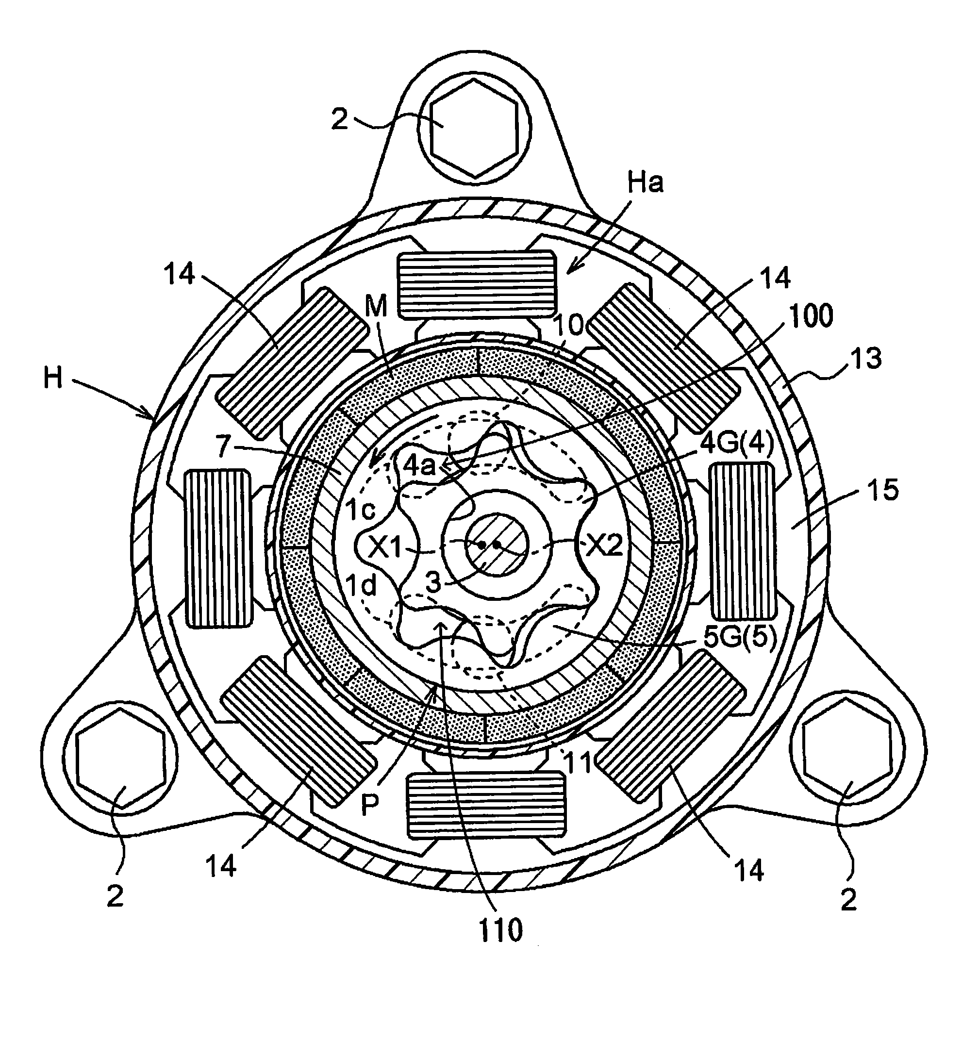
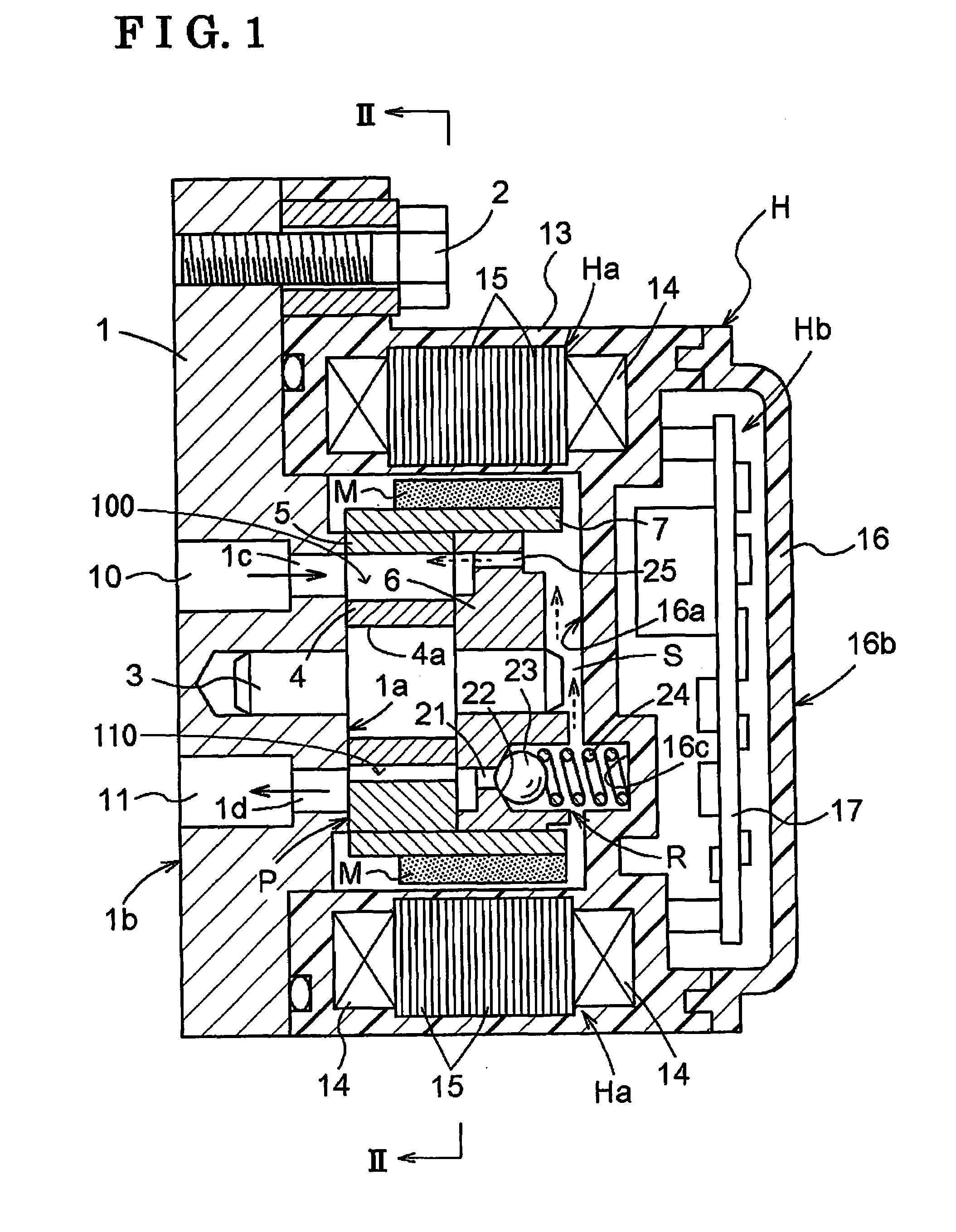
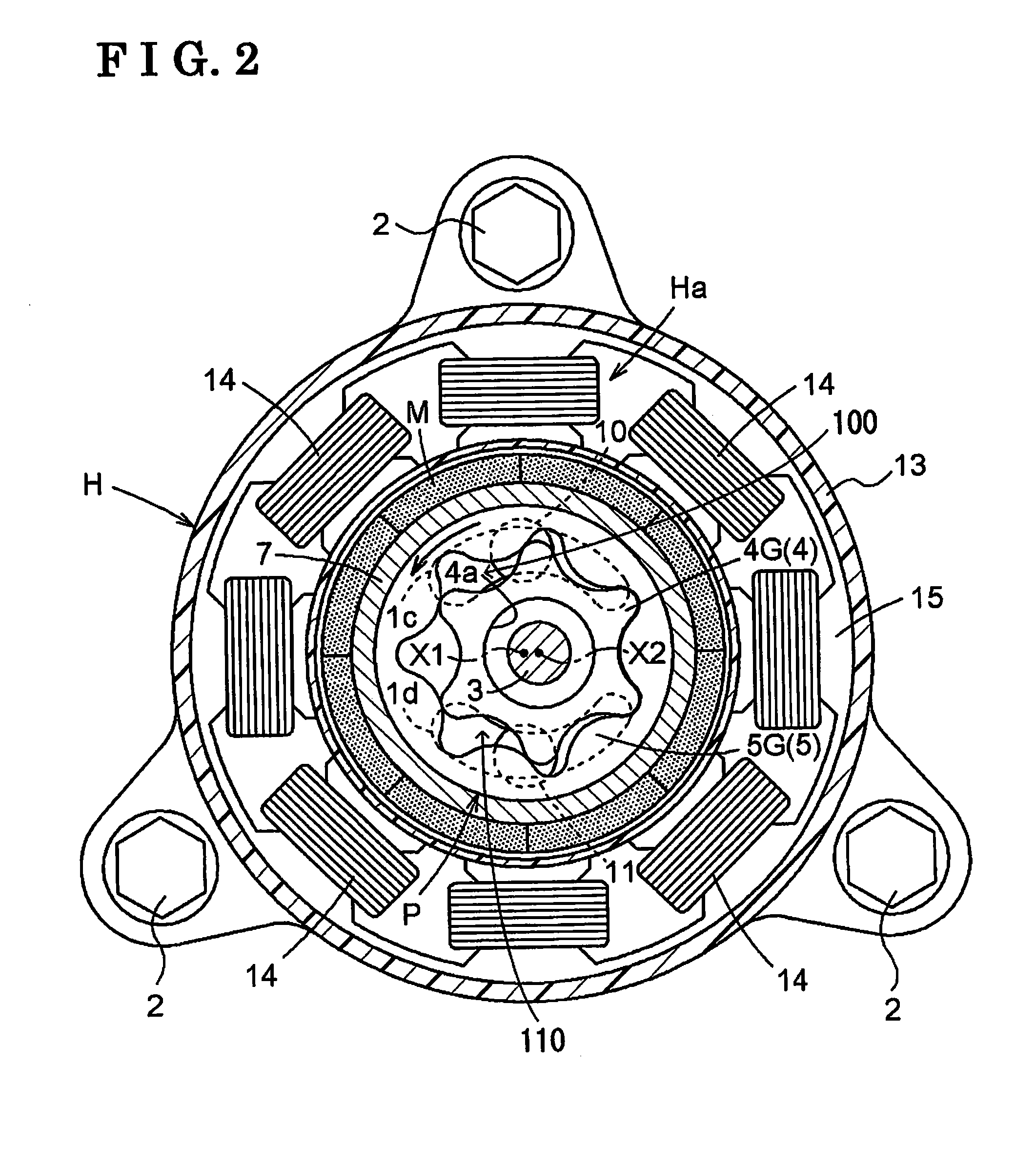
[0017]An embodiment of an electric pump according to the present invention is described hereinbelow with reference to the attached drawings. As illustrated in FIGS. 1, 2, and 3, an electric pump is configured by connecting and fixing a housing H to a base member 1 by means of bolts 2. A trochoid-type pump portion P is supported by and fitted into the housing H. The electric pump is applied for supplying lubricating oil (fluid), for example, to an automobile engine.

[0018]The pump portion P includes the base member 1, a shaft 3, an inner rotor 4, an outer rotor 5 and a side plate member 6. The base member 1 is formed into a plate shape. One end of the shaft 3 is inserted into and fixed at the base member 1. The inner rotor 4 is rotatably supported by an intermediate portion of the shaft 3. First teeth 4G are provided at an outer circumference of the inner rotor 4. Second teeth 5G are provided at an inner circumference of the outer rotor 5. The first teeth 4G are engaged with the secon...


PUM


Abstract

According to an aspect of the present invention, an electric pump includes: a housing; an outer rotor; an inner rotor; a base member facing one side surface of the outer rotor and one side surface of the inner rotor; a side plate member, having a facing surface facing the other side surface of the outer rotor and the other side surface of the inner rotor and a non-facing surface opposed to the facing surface; a shaft; a suction port; a discharge port; a negative pressure applied region; a positive pressure applied region; and a relief valve, discharging the fluid from the positive pressure applied region to a non-facing surface side of the side plate member when a pressure applied at the positive pressure applied region exceeds a predetermined value.

Description

CROSS REFERENCE TO RELATED APPLICATIONS[0001]This application is based on and claims priority under 35 U.S.C. § 119 to Japanese Patent Application 2008-001482, filed on Jan. 8, 2008, the entire contents of which is incorporated herein by reference.FIELD OF THE INVENTION[0002]This invention relates to an electric pump including a pump portion having an outer rotor and an inner rotor.BACKGROUND[0003]A known electric pump is disclosed in JP2006-336469A (which is hereinbelow referred to as reference 1). According to the electric pump in reference 1, a trochoid-type pump portion is configured by providing an inner rotor in an outer rotor. A rotor is formed by providing a permanent magnet along an outer circumferential surface of the outer rotor. A casing is provided at a position surrounding the outer rotor. A stator, around which plural wires are respectively wound, is provided at a portion of the casing surrounding the outer rotor. Electric power is supplied to each of the wires of the...

Claims


Application Information

Patent Timeline
Patent Type & Authority Applications(United States)
IPC IPC(8): F04C2/10H02K9/19F04C29/04
CPCF04C2/086F04C2/102F04C11/008F04C2240/30F04C15/0026F04C15/0042F04C14/265
Inventor NAKAYOSHI, HIDEKI
Owner AISIN SEIKI KK
Why Eureka
Try Eureka