Golf putter

Inactive Publication Date: 2009-07-09
RALEY KENNETH
View PDF29 Cites 3 Cited by
  • Summary
  • Abstract
  • Description
  • Claims
  • Application Information

AI Technical Summary

Benefits of technology

[0003]The present invention provides a golf putter head that is designed to improve a golfer's golf putt. The putter head is in the shape of a right cylinder with the circular ends each providing a striking face. The golfer aligns one of the striking faces with the ball. The diameter of the striking face is slightly smaller than the ball diameter such that the center of the striking face may be aligned with the center of the ball when the putter is lifted slightly off the ground. The golfer swings the putter head which mo

Problems solved by technology

Despite practicing this stroke, many golfers still strike the ball

Method used


Image

  • Golf putter
  • Golf putter

Examples


Example

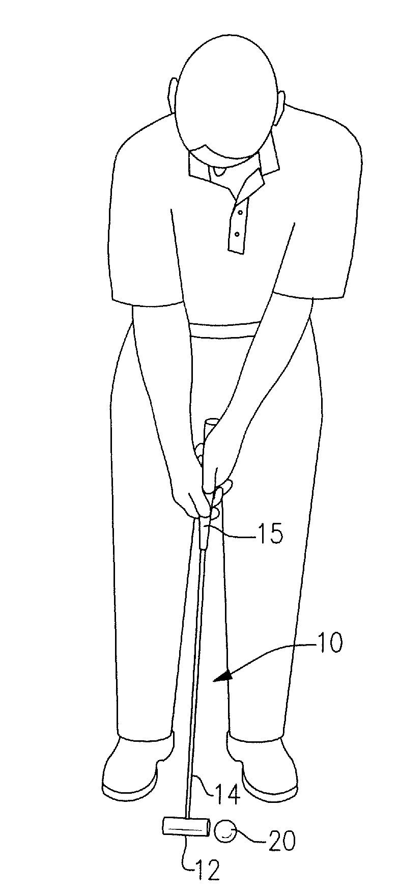
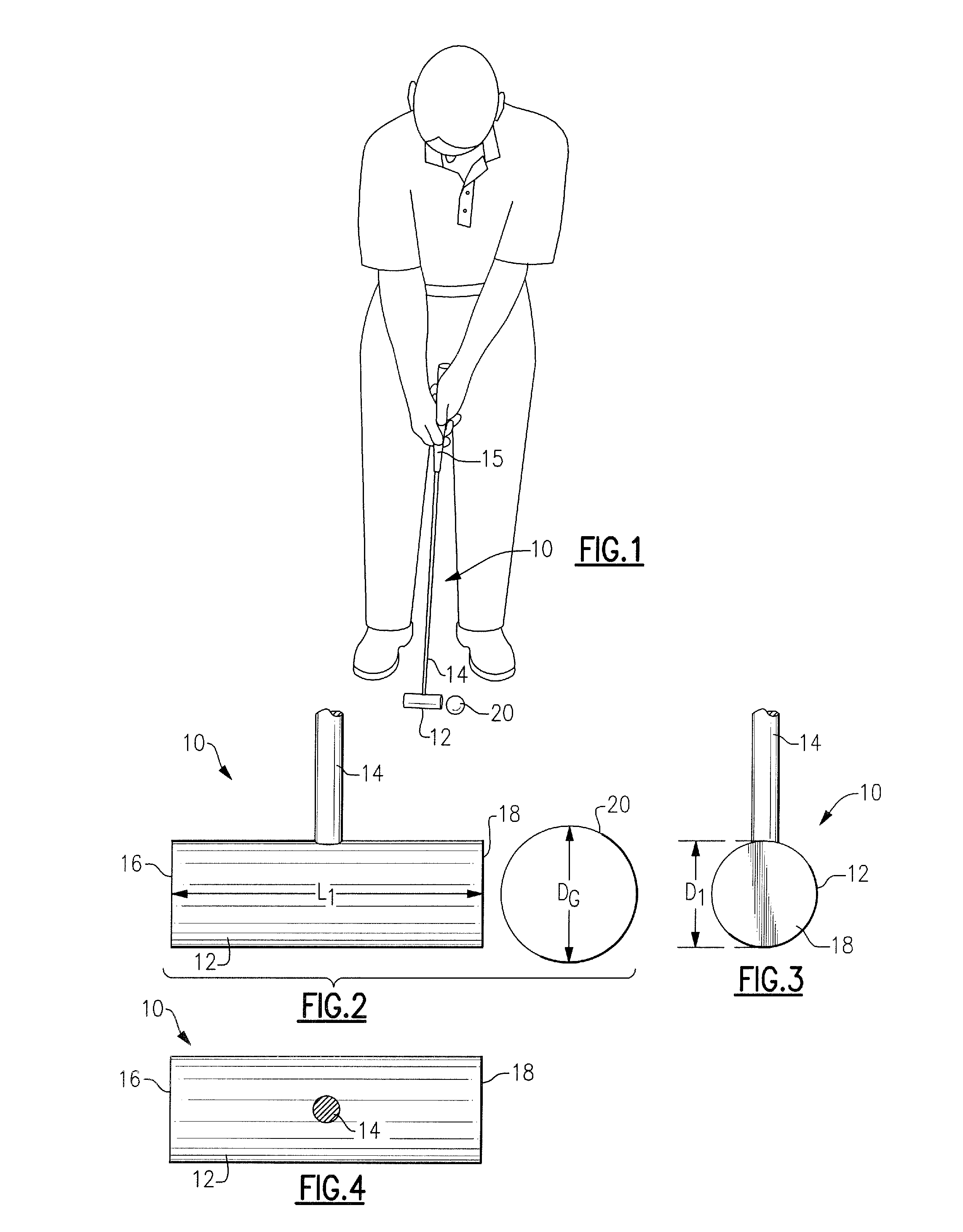
[0008]Referring to the drawings, there is seen a golf putter 10 having a putter head 12 and shaft 14. The putter head 12 is in the shape of a right cylinder having circular striking faces 16 and 18 at either end thereof whereby either striking surface may be used to strike the ball. The shaft 14 is preferably positioned perpendicular to the head and halfway between striking faces 16 and 18 although this may vary depending on the desires of the golfer. The shaft 14 is affixed to the putter head 12 by any suitable means, e.g., by drilling a hole into the putter head and threading the end of the shaft into the drilled hole.

[0009]The putter head 12 of the present invention may be provided as a solid cylinder with no hole for the shaft. The golfer then may choose to place their own style and length of shaft in a position of their own choosing in the golf putter head. The golfer may also select their own grip 15 for the shaft 14.

[0010]A typical U.S. golf ball 20 is 1.625 inches in diamete...


PUM


Abstract

A golf putter for training in the shape of a right cylinder is made out of good weight material such as solid brass. The weight of the putter conditions the golfer's muscles and inhibits the golfer from decelerating during the stroke. The putter includes opposite circular striking faces and is swung in the manner of a pendulum whereby the golfer's finger and arm muscles are conditioned during putting.

Description

BACKGROUND OF THE INVENTION [0001]The present invention generally relates to the sport of golfing, and more particularly relates to a golf putter head designed to improve a golfer's putting stroke.[0002]The putter is the club used on the green to hit the ball into the hole. There have been many different styles of putter heads with most present day putter heads being elongated with a striking face between either end of the head. The golfer aligns the striking face of the putter head with the golf ball and swings the putter to strike the ball with the striking face of the putter head. The putting stroke must hit the ball with the striking face at the correct angle or the ball will miss the hole. Despite practicing this stroke, many golfers still strike the ball with the striking face of the putter head at the incorrect angle. What is needed is a golf putter head that is designed to improve a golfer's golf putt.SUMMARY OF THE INVENTION [0003]The present invention provides a golf putte...

Claims


Application Information

Patent Timeline
IPC IPC(8): A63B69/36A63B53/04
CPCA63B53/0487A63B2209/00A63B2053/0408A63B53/0408
Inventor RALEY, KENNETH
Owner RALEY KENNETH
Why Eureka
Try Eureka