Medical Instrument For Rod Positioning

Inactive Publication Date: 2009-07-09
RACHIOTEK
View PDF22 Cites 42 Cited by
  • Summary
  • Abstract
  • Description
  • Claims
  • Application Information

AI Technical Summary

Benefits of technology

[0011]The disclosed apparatus generally includes (i) a handle element positioned and configured for manipulation, (ii) a first jaw element in communication with the handle element, and (iii) a second jaw element in communication with the handle element. The first and second jaw elements are positioned distally relative to the handle element and the handle element is adapted to effect relative motion between the first and second jaw elements. Each of the jaw elements define abutment faces that are substantially aligned in a confronting relati

Problems solved by technology

For example, since the support rod is fixed in orientation relative to such forceps designs, an operating surgeon is limited in his or her range/ability to pivot or otherwise manipulate the support rod into place.
Furthermore, the act of pivoting/manipulating the forceps relative to a patient in order to position/align the support rod in a desired orientation creates added dimen

Method used


Image

  • Medical Instrument For Rod Positioning
  • Medical Instrument For Rod Positioning
  • Medical Instrument For Rod Positioning

Examples


Example

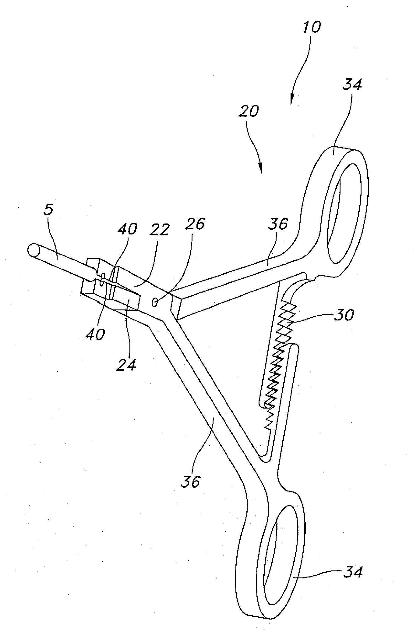
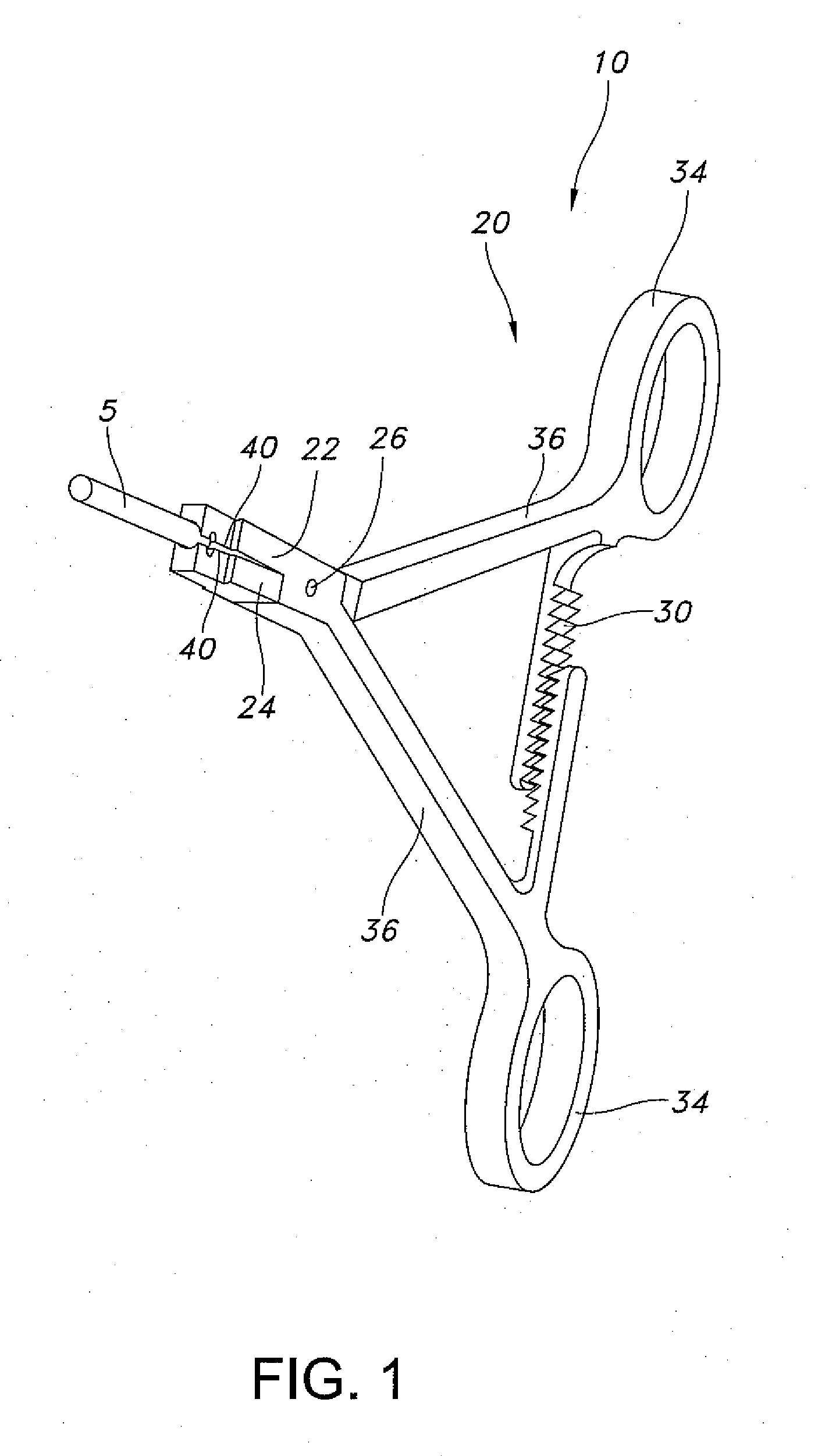
[0028]The disclosed apparatus, systems, and methods relate to manipulation, e.g. pivoting, of a rod-shaped element using an advantageous rod positioning assembly as disclosed herein. More particularly, exemplary embodiments of the disclosure involve pivoting a rod-shaped element, initially gripped axially (relative to and) by a rod positioning assembly, without the need to pivot the handle of the rod positioning assembly and / or release the rod-shaped element.

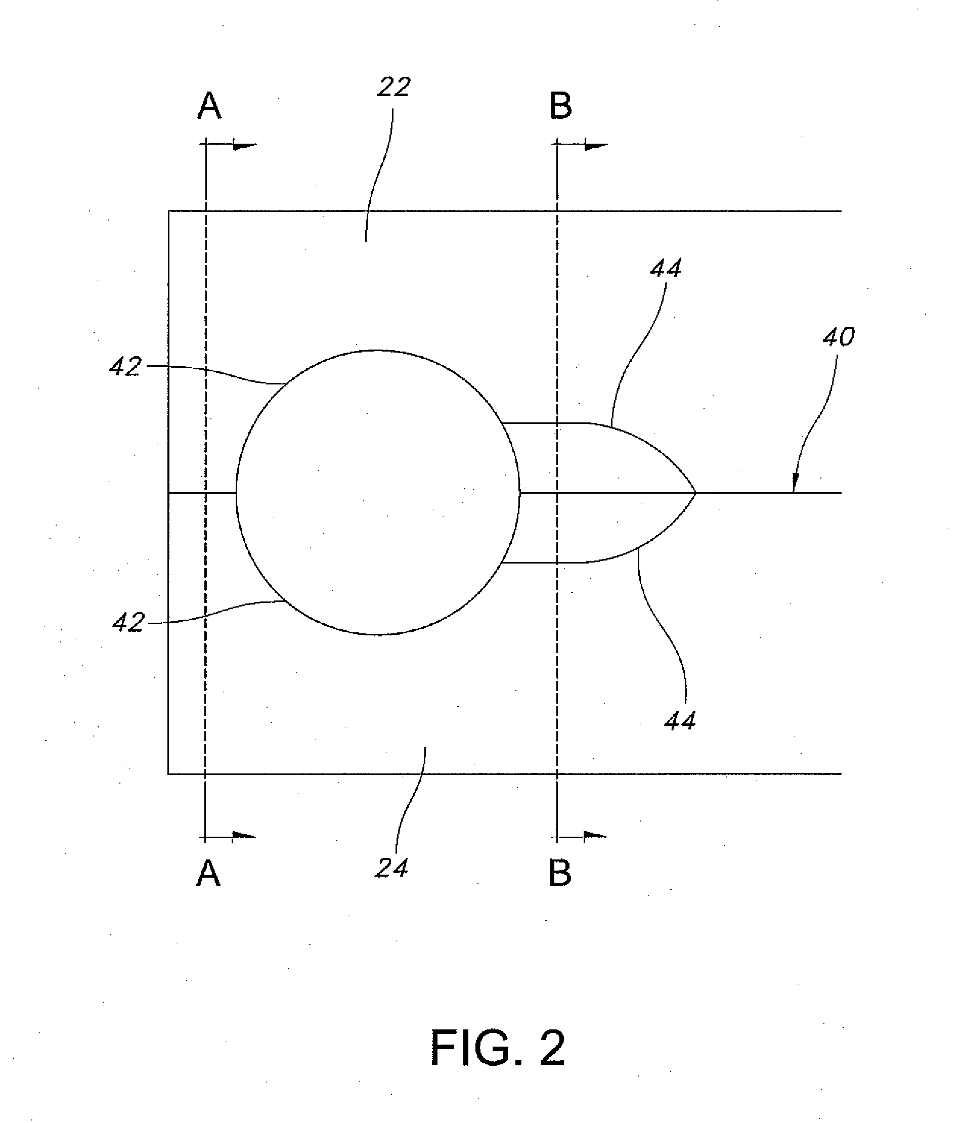
[0029]With initial reference to FIG. 1, a perspective view of an exemplary rod positioning assembly 10 is depicted gripping a rod-shaped element 5. The rod positioning assembly 10 includes a handle element 20, a first jaw element 22 and a second jaw element 24. Each of the first and second jaw elements 22 and 24 defines an abutment face 40. The first and second jaw elements 22 and 24 are positioned distally relative to the handle element 20 and are adapted to be moved relative to each other through manipulation of the handle ele...


PUM


Abstract

Apparatus, systems and methods relating to manipulation, e.g. pivoting, of a rod-shaped element using a rod positioning assembly are disclosed. A rod-shaped element is initially gripped axially (relative to and) by a rod positioning assembly and then pivoted into a transverse orientation without pivoting the rod positioning assembly and/or releasing the rod-shaped element. Rod positioning assemblies include a handle element and a pair of jaw elements in communication therewith. The jaw elements are positioned distally relative to the handle element and the handle element is adapted to effect relative motion between the first and second jaw elements. The abutment faces of the jaw elements define a pair of axially aligned notches at or near the distal ends of the first and second jaw elements, a pair of traversely aligned central wells that define a circular opening that extends transversely across the jaw elements, and a pair of grooves that open up to a single transverse side of the jaw elements.

Description

BACKGROUND[0001]1. Technical Field[0002]The present disclosure is directed towards apparatus, systems and methods for implantation and manipulation of orthopedic devices. More particularly, exemplary embodiments of the present disclosure relate to apparatus, systems and methods for implantation and manipulation of an elongated member, e.g., a rods relative to an anatomical structure, e.g., the spine.[0003]2. Background Art[0004]In many applications, particularly those relating to orthopedic surgery and correctional techniques, elongated members are implanted into a patient interconnecting at both ends relative to one or more bones, one or more bone anchoring elements, fracture sites, and other similar locations. These elongated members may include but are not limited to support rods, pins, braces, struts and the like.[0005]Corrective spinal surgery is an exemplary clinical application that involves implantation of elongated members, e.g., rods, pins, struts, braces or the like. Thus...

Claims


Application Information

Patent Timeline
IPC IPC(8): A61B17/56
CPCA61B17/7083A61B17/282
Inventor ZLOCK, STEPHEN W.WALTERS, CARMEN
Owner RACHIOTEK
Why Eureka
Try Eureka