

Code error detecting device, wireless system and code error detecting method
a code error and wireless system technology, applied in the field of code error detection apparatus, radio system and error detection method, can solve the problems of signal degradation, bit error upon demodulation, etc., and achieve the effect of more accurate detection of code errors
- Summary
- Abstract
- Description
- Claims
- Application Information
AI Technical Summary
Benefits of technology
Problems solved by technology
Method used
Image

Examples
embodiment 1
[0050]FIG. 4 is a block diagram showing a configuration example of a wireless communication system according to Embodiment 1 of the present invention.
[0051]In FIG. 4, a wireless communication system is configured including first terminal 100 and second terminal 200. These terminals 100 and 200 are, for example, mobile telephones, audio visual devices and personal computers.
[0052]First terminal 100 is configured including transmitting section (transmitting apparatus) 110 and receiving section (receiving apparatus: error code detecting apparatus) 120. Meanwhile, transmitting section 110 and receiving section 120 may be implemented as, for example, LSI or may be contained on a single chip.
[0053]Transmitting section 110 has transmission data holding section 111 that stores transmission data T1 on a temporary basis and mapping section 112 that extracts transmission data T1 from transmission data holding section 111 at a predetermined timing and allocates codes to transmission data T1. Th...
embodiment 2
[0093]Embodiment 2 differs from Embodiment 1 where detected data is acquired using one threshold voltage V1, in acquiring detected data using two different threshold voltages V1 and V2 (for example, V12). V1 will be referred to as “the first threshold voltage” and V2 will be referred to as “the second threshold voltage” below.
[0094]First terminal 100 and second terminal 200 in Embodiment 2 have receiving section 120A instead of receiving section 120 in Embodiment 1. Therefore, the configuration of receiving section 120A of first terminal 100 will be focused upon and described below.
[0095]FIG. 7 is a block diagram showing a configuration example of receiving section 120A according to Embodiment 2 of the present invention. Meanwhile, in Embodiment 2, the same reference numerals will be assigned to the same parts as in Embodiment 1 and repetition of description will be omitted.
[0096]Receiving section 120A shown in FIG. 7 has pulse detector 124A and data controlling section 130A instead...
embodiment 3
[0118]Embodiment 3 differs from Embodiments 1 and 2 where encoding is carried out using an RZ (return to zero) code to a time slot of one bit, in carrying out encoding using a Manchester code for dividing the time slot of one bit into two and inserting codes which invert bits. That is, in mapping section 112 (see FIG. 4) of transmitting section 110, transmission data T1 is encoded using the Manchester code. For example, mapping section 112 allocates codes of “10” if transmission data is “0” and, on the other hand, allocates codes of “01” if transmission data is “1.” The other configuration of transmitting section 110 is the same as in Embodiments 1 and 2.
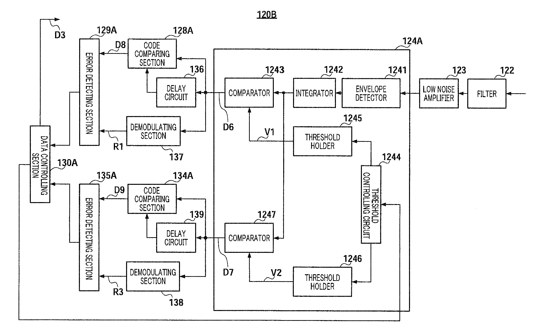
[0119]Next, the configuration of the receiving section according to Embodiment 3 will be described. First terminal 100 and second terminal 200 in Embodiment 3 have receiving section 120B instead of receiving section 120 in Embodiment 1. Receiving section 120B will be focused upon and described below.
[0120]FIG. 10 is a block diagram ...
PUM
 Abstract
Description
Claims
Application Information