Pre-cast concrete column and method of fabrication

a pre-cast concrete and column technology, applied in the field of concrete columns, can solve the problems of weakening the concrete column formed therefrom, voids and pockets between the five pieces of rebar, and crevices that are difficult to fill with concrete, and achieve the effect of easy flow and easy flow

Inactive Publication Date: 2009-07-16
BAUMANN HANNS U
View PDF63 Cites 19 Cited by
  • Summary
  • Abstract
  • Description
  • Claims
  • Application Information

AI Technical Summary

Benefits of technology

[0012]The column grid may have a generally square or rectangular configuration. The column grid may define four corners. The column cage may have less than twelve vertically extending rebars charged through the plurality of column grids. Preferably, the column cage has four vertically extending rebars charged through the plurality of column grids. Even though the column cage has less vertically extending rebars compared to the prior art, the concrete column formed by the column cage is more rigid compared to prior art concrete columns formed by the method discussed in the background. One benefit of having less vertically extending rebars charged through the column grids is that the wet concrete is able to more easily flow through the plurality or lattice work of column grids and vertically extending rebars to fill any voids or pockets of air that might be formed during the concrete pouring process.
[0013]The concrete column formed with the column cage discussed herein is more rigid compared to the prior art concrete column. As such, an individual column cage may be taller compared to prior art column cages. Accordingly, less interconnections between column cages are needed to reach a particular height. Moreover, less couplers are required to join the vertically extending rebars of adjacent column cages.
[0014]The construction of the column cages discussed herein produces a column cage which is generally lighter but stronger compared to prior art column cages discussed in the background.

Problems solved by technology

One deficiency of the prior art lattice work of grids and vertically extending rebars is that there are many crevices, voids and pockets between the five pieces of rebars that make up the grid, as shown in FIG. 2.
These voids are typically very difficult to fill with concrete.
Unfortunately, these voids may not be filled even with vibration thereby weakening the concrete column formed therefrom.
Another deficiency in the lattice work of grids and rebars is the enormous amount of weight of the material required to form the concrete column.
The overlapping rebars add unnecessary weight to the concrete column.
Moreover, the wire ties used to hold the rebars together add additional unnecessary weight to the concrete column.
Unfortunately, due to the viscosity of the wet concrete, the concrete may not be able to work its way around each and every protuberance within the lattice work of grids and vertically extending rebar.
Another deficiency in the lattice work of grids and rebars is the inaccuracy of the placement of the five rebars that make up one grid and placement of the twelve vertically extending rebars within the plurality of vertically stacked grids.
Unfortunately, bending rebar is not accurate, and thus, the five rebars are not accurately placed in relation to each other.
Moreover, the inaccuracy of the bent rebars is further accentuated because they are held together by wire ties since the lattice work of grids is inaccurate to begin with, the twelve vertically extending rebars are inaccurately placed within the lattice work of grids.
The resulting concrete column formed from the column cage is not very rigid.
Thus, the resulting concrete column is subject to breakage or failure upon the occurrence of an earthquake or other force.

Method used


Image

  • Pre-cast concrete column and method of fabrication
  • Pre-cast concrete column and method of fabrication
  • Pre-cast concrete column and method of fabrication

Examples


Embodiment Construction

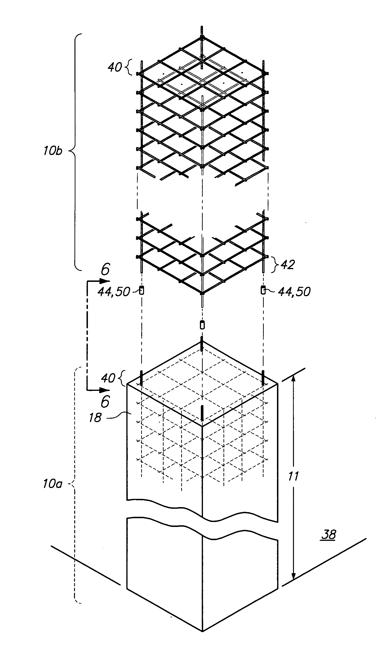
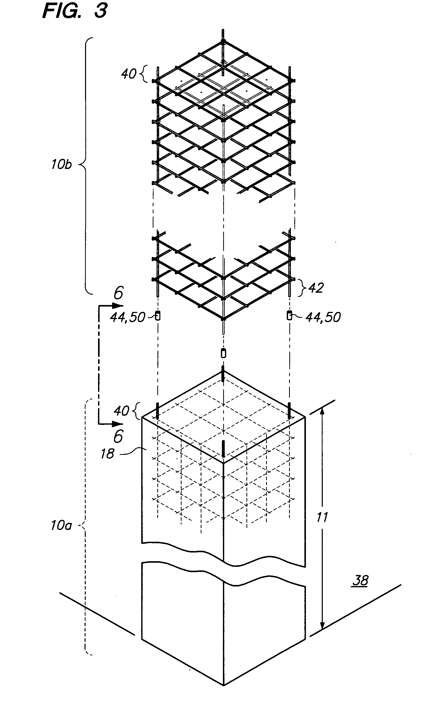
[0023]Referring now to FIG. 3, column cages 10a, b are shown. Each of the column cages 10a, b may be fabricated in a manner so as to be longer than a standard prior art column cage. In particular, prior art column cages are typically fabricated in thirty feet length. In contrast, the column cages 10a, b shown in the drawings may be fabricated in lengths 11 longer than thirty feet. Since rebar is typically provided in sixty feet length, the column cages 10a, b may each be fabricated up to sixty feet long. However, in the event that rebar greater than sixty feet can be provided, the column cages 10a, b may each be fabricated greater than sixty feet and up to the length of the rebar. Since the column cages 10a, b may be fabricated in a length 11 longer than standard prior art column cages, fewer column cages 10a, b are interconnected to each other to reach a required height. Accordingly, less rebar couplers 44, 50 are needed to couple column cages 10a, b together and also greater heigh...


PUM


Abstract

A column cage may comprise a plurality of column grids. The column grids may be formed with a plurality of longitudinal rebars. Also, the column grid may have a plurality of transverse rebars attached atop the plurality of longitudinal rebars. The transverse rebars may be attached to the longitudinal rebars. Four vertically extending rebars may be charged through the plurality of column grids at the four corners of column grids. The column grid may be held firmly to the vertically extending charged rebars with wire ties. Additionally, adjacent column cages may be connected to each other with a swedged on coupler.

Description

CROSS-REFERENCE TO RELATED APPLICATIONS[0001]This application is related to U.S. Pat. No. 5,305,573, filed on Jun. 3, 1992; U.S. Pat. No. 5,392,580, filed on May 6, 1992; and U.S. Pat. No. 5,459,973, filed on Apr.22, 1994, the entire contents of which are expressly incorporated herein by reference.STATEMENT RE: FEDERALLY SPONSORED RESEARCH / DEVELOPMENT[0002]Not ApplicableBACKGROUND[0003]The present invention relates to a concrete column, and a method for forming the same.[0004]Prior art concrete columns are formed from a lattice work of rebars. In particular, vertically extending rebars are held in position by a plurality of equally spaced apart grids, as shown in FIG. 1. The grids are formed by bending short lengths of rebar and are held together by wire ties. For example, as shown in FIGS. 1 and 2, a square grid for holding in place twelve vertically extending rebars is shown. The grid is comprised of five different pieces of rebar. The first rebar is bent in a generally square sha...

Claims


Application Information

Patent Timeline
Patent Type & Authority Applications(United States)
IPC IPC(8): E04B1/18E04B1/19E04H12/12E04B1/21
CPCE04C5/0604E04C3/34
Inventor BAUMANN, HANNS U.
Owner BAUMANN HANNS U
Why Eureka
Try Eureka