Work table having adjustable hose support

Inactive Publication Date: 2009-07-16
YU BEN
View PDF14 Cites 16 Cited by
  • Summary
  • Abstract
  • Description
  • Claims
  • Application Information

AI Technical Summary

Benefits of technology

[0012]The primary objective of the present invention is to provide a work table including a supporting device for adjustably attaching and supporting a hose to the work table an

Problems solved by technology

However, normally, the hose member for discharging the cut chips is not supported in place and may interfer the operation of the work table.
However, similarly, the hose member coupled to the dust chute for discharging the dust is also not supported in place

Method used


Image

  • Work table having adjustable hose support
  • Work table having adjustable hose support
  • Work table having adjustable hose support

Examples


Example

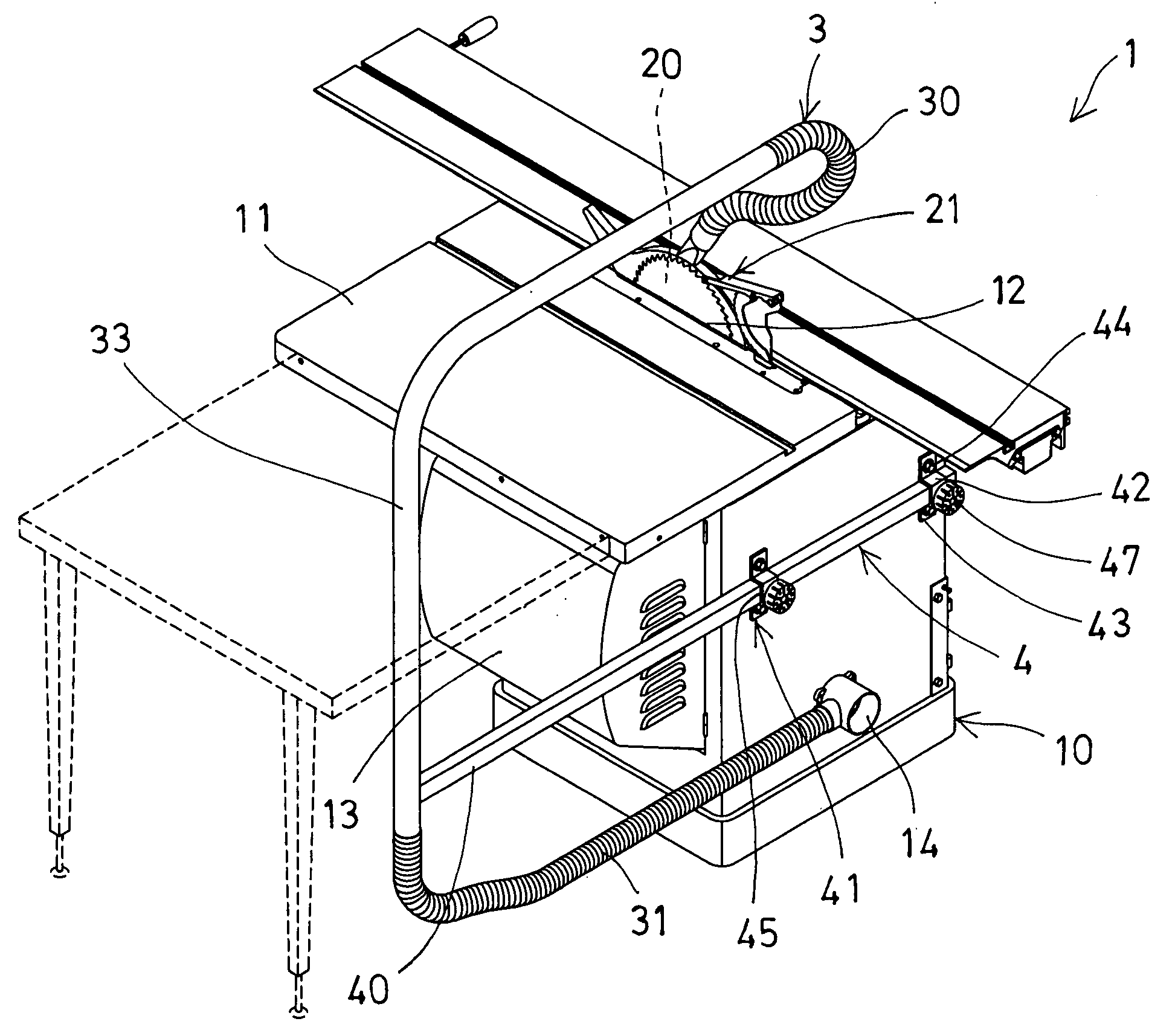
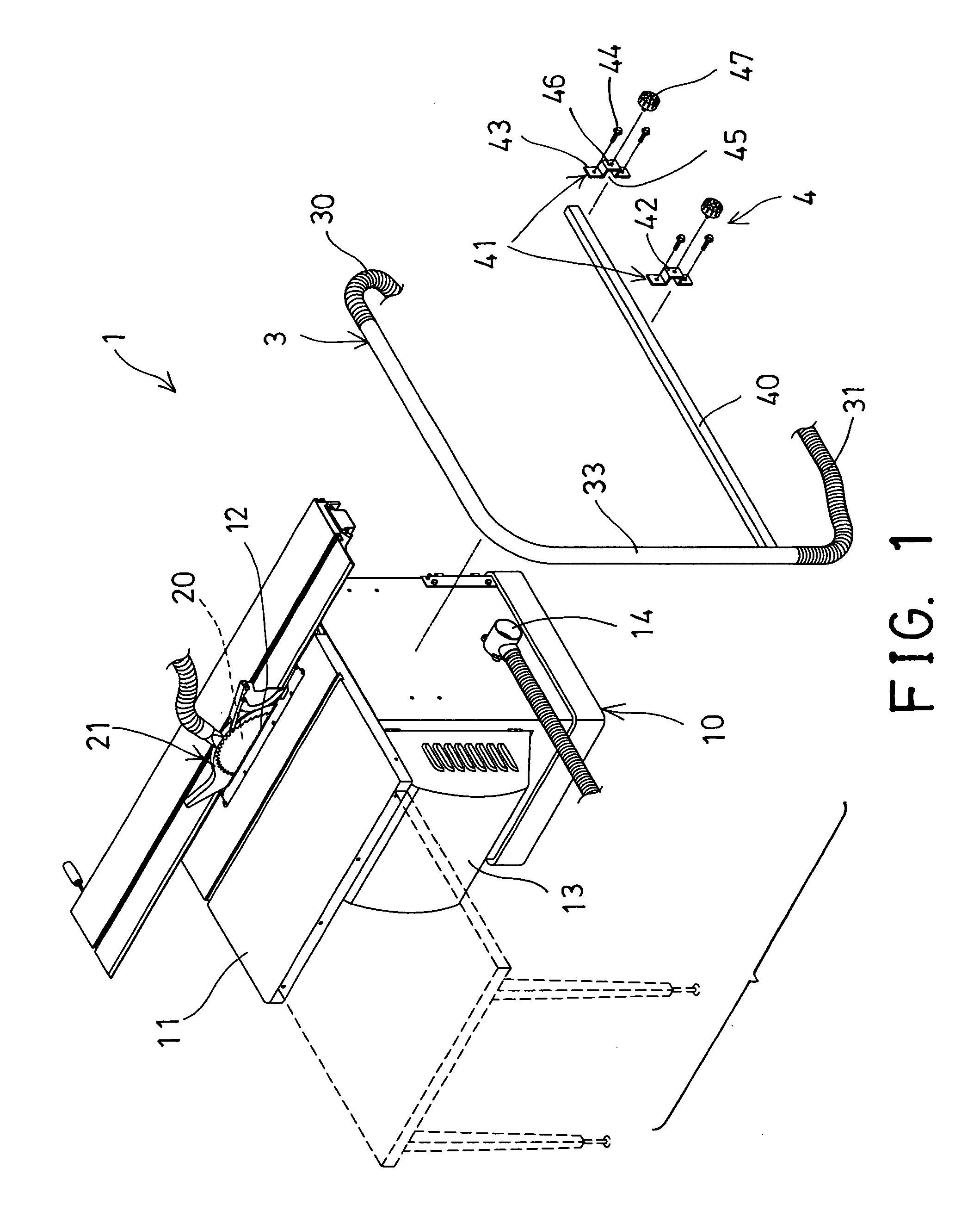
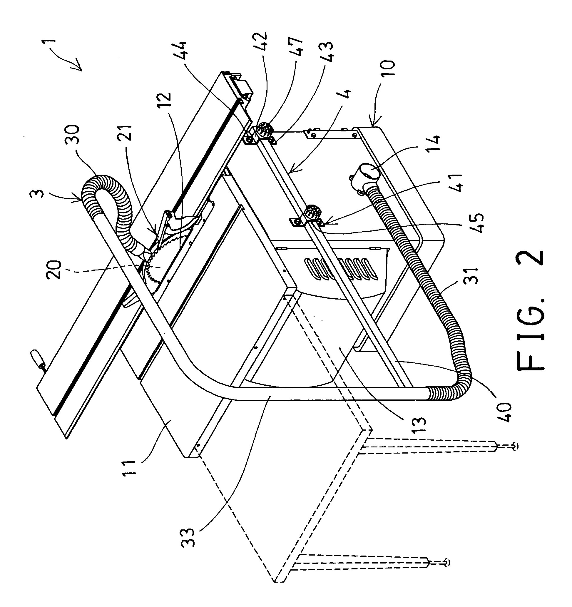
[0022]Referring to the drawings, and initially to FIGS. 1-3, a work table 1 in accordance with the present invention comprises a base table body 10 including a table plate 11 disposed on top for supporting work pieces 80 (FIGS. 3, 4), and including a slot 12 formed in the upper portion of the table plate 11 for receiving or attaching a machining tool device 20, such as a table saw or circular saw 20, a round saw, a milling tool, a cutting device, a grinding member or the like which may be used for working or machining the work pieces 80. A safety hood or shield 21 may further be provided and engaged with or onto the machining tool device 20 for covering or shielding the machining tool device 20 and for gathering or collecting or discharging the cut chips or the dust that may be generated by the tool device 20.

[0023]The table body 10 includes a door 13 openably attached thereto and rotatable or openable relative to the table body 10 (FIGS. 3, 4) for selectively reaching or entering i...


PUM

PropertyMeasurementUnit
Flexibilityaaaaaaaaaa

Abstract

A work table includes a table plate having a slot for attaching a tool device, and a coupler for coupling to a vacuum device, a shield engaged onto the tool device for shielding the tool device and for gathering the dust, a hose coupling device coupled between the shield and the coupler, and a supporting device for adjustably supporting the hose coupling device to the work table at any required position. The hose coupling device may include two flexible hose members coupled to the shield and the coupler, and a rigid hose member coupled between the flexible hose members, and a rod extended from the rigid hose member for adjustably securing to the table with one or more brackets.

Description

BACKGROUND OF THE INVENTION[0001]1. Field of the Invention[0002]The present invention relates to a work table, and more particularly to a work table including a supporting device for adjustably attaching and supporting a hose to the work table and for suitably positioning the hose to the work table at the required or the predetermined position and for preventing the hose from interferring the operation of the work table.[0003]2. Description of the Prior Art[0004]Typical work tables comprise a base table body and a machining tool device, such as a table saw, a round saw, a milling tool, a cutting device, a grinding member or other machining tools supported in the base table body for working or machining the work pieces.[0005]For example, U.S. Pat. No. 5,040,444 to Shotani et al. discloses one of the typical saw blade position setting apparatuses comprising a circular saw supported in a support frame, a safety cover engaged onto the circular saw for shielding the cut chips and for pre...

Claims


Application Information

Patent Timeline
IPC IPC(8): A47B41/06B27B5/29A47B37/00
CPCB23D59/006Y10T83/7734Y10T83/773Y10T83/207
Inventor YU, BEN
Owner YU BEN
Why Eureka
Try Eureka