Retractable lifeline safety device

a safety device and lifeline technology, applied in the direction of safety belts, building rescue, hoisting equipment, etc., can solve the problems of increasing the overall complexity and manufacturing cost, limited movement of conventional retraceable lifelines, etc., to reduce manufacturing costs, overcome deficiencies and shortcomings, and alleviate the effect of many unnecessary internal components

Inactive Publication Date: 2009-07-16
SIGMA IND
View PDF6 Cites 103 Cited by
  • Summary
  • Abstract
  • Description
  • Claims
  • Application Information

AI Technical Summary

Benefits of technology

[0008]In view of the shortcomings of current retractable lifelines, a need exists for an improved retraceable lifeline. The present invention is designed to overcome the deficiencies and shortcomings of the devices described above. The present invention is designed to reduce the manufacturing costs and alleviate much of the unnecessary stress on the internal components caused by friction and striking forces.
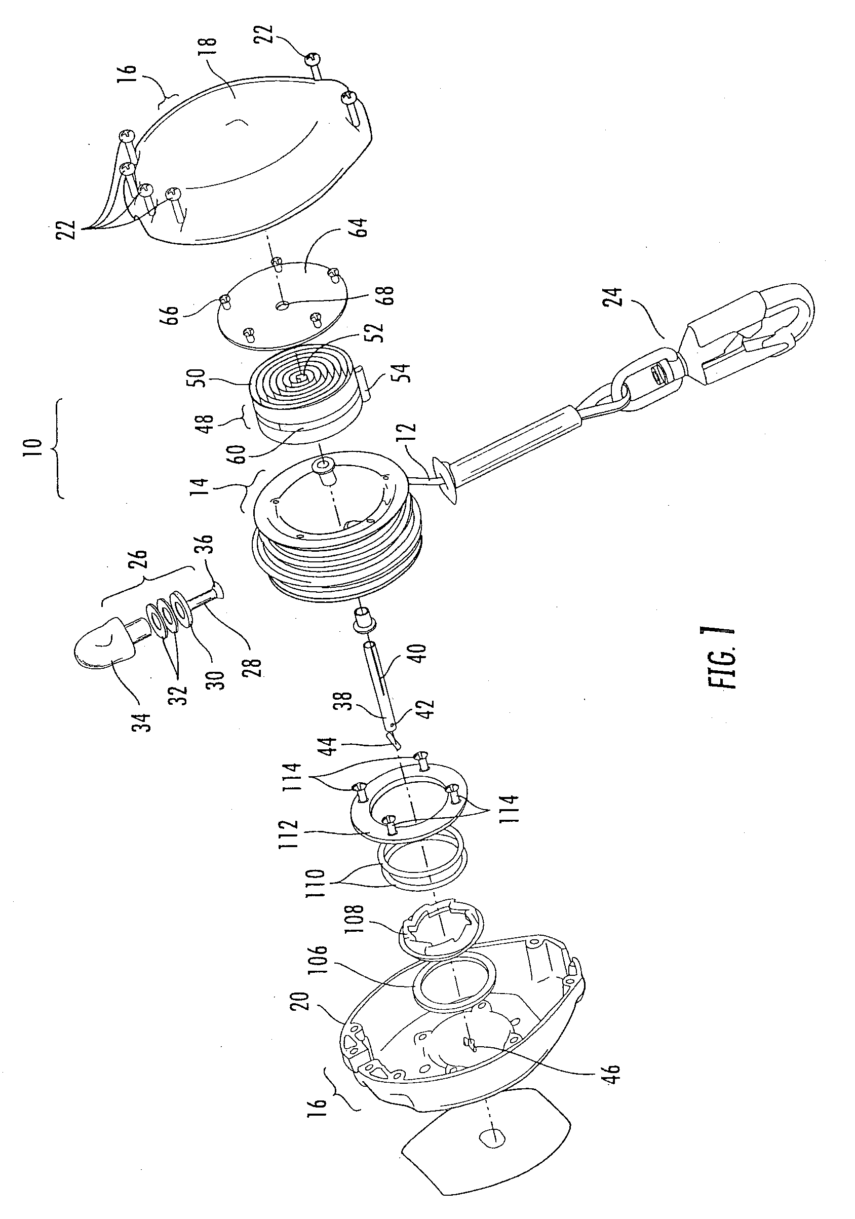
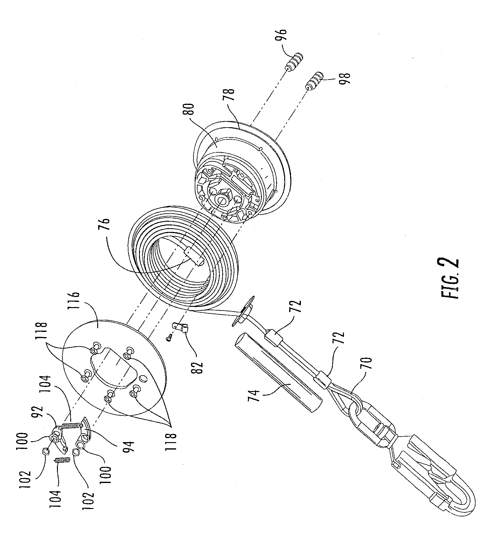
[0011]The end of the cable that attaches to the hook forms a loop by looping back on itself and being secured by at least one, but preferably two duplex ferrules. Such loop attaches to the hook and protrudes from a cushion. The opposite end of the cable is secured inside the housing to the spool by means of a cable stop. A portion of the cable, the reserve cable, is fixed to a spool drum about which the cable winds and unwinds. On the end of the reserve cable opposite to the cable stop, a clamp secures the reserve cable to the spool drum. The clamp is preferably attached to the spool drum by a clamp screw accessed from the exterior of the spool drum. The clamp screw attaches to a clamp flat. In the event of a fall in which the cable extension reaches the reserve cable, the screw, the screw hole threads, or the clamp flat breaks and allows the reserve cable to be withdrawn from the spool, thus providing additional time to slow the rate of extrusion of the cable from the spool.
[0012]On the lower end of the housing where the cable exits, a cable guide separates the cable from the body of the housing and prevents the cable from rubbing against the housing while it is withdrawn and retracted. The cable guide has a cable guide tab protruding around its perimeter for engagement with the housing. The cable guide tab is held in place, or nested, within the housing by a cable guide mount.
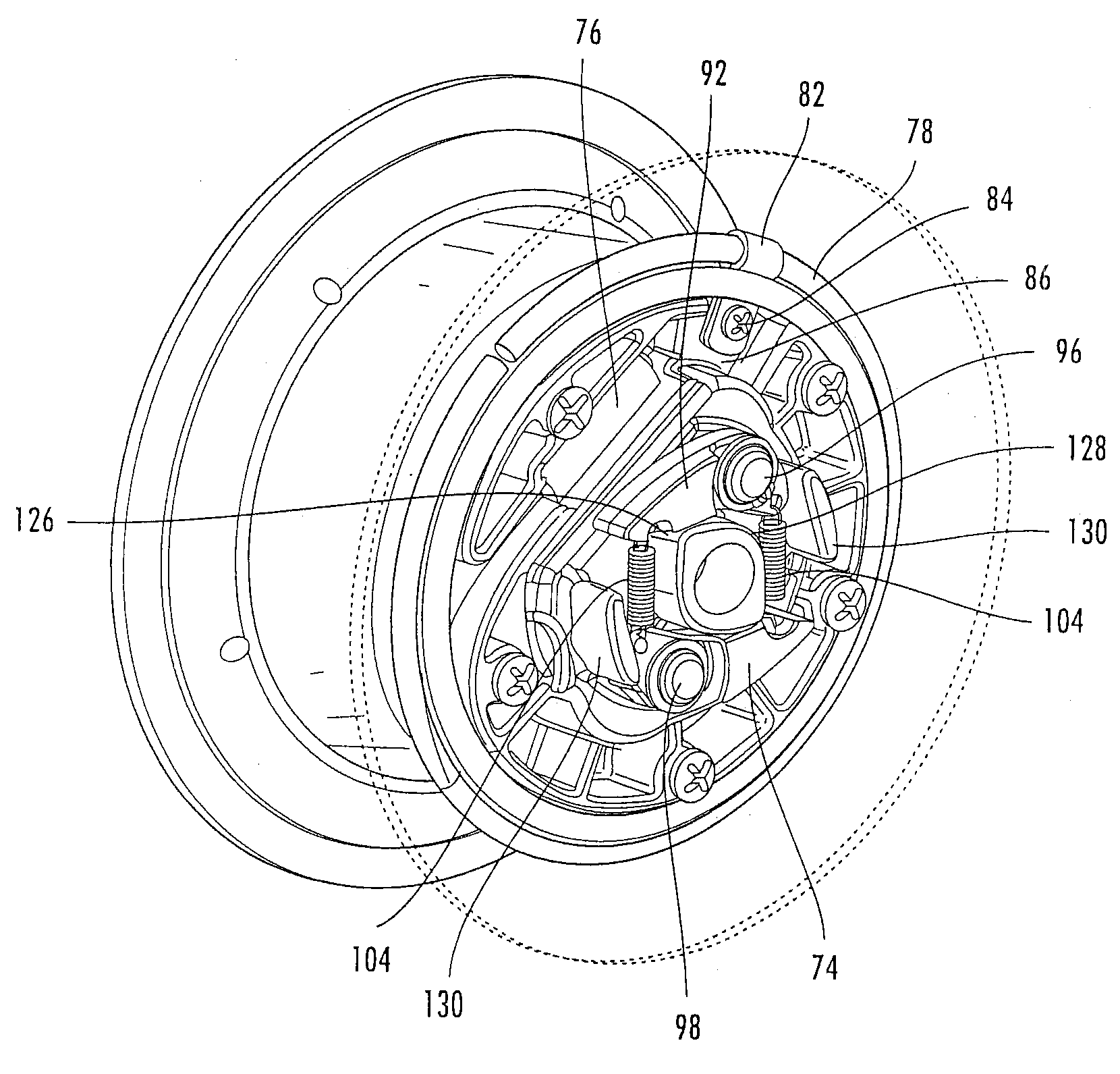
[0013]Within the spool and adjacent to the power spring are two pawls rotatably mounted on corresponding pawl axles. The pawls are held on the pawl axles by pawl washers and snap rings. The rotation of the pawls are arrested by pawl springs that attach the tip of the pawls. The pawl springs exert enough force on the ends of the pawls to keep their position stationary. Pawls stops are provided to limit the extent of the rotation of the pawls. A pair of spring guards are attached to the axle in opposite relation between the pawls such that the spring guards provide protection to the pawl springs.
[0017]In all exemplary embodiments, the retractable lifeline is easier to manufacture and maintain. Further, the present invention provides an audible and tactile indicator of impending lockup by utilizing a sprocket with one or more distinct teeth. Normally, the sprocket consists of a plurality of teeth each identical and spaced so the pawls may enter into a root area thereby engaging the sprocket. The present invention alters a tooth on the sprocket to extend slightly beyond the normal teeth. A tooth ramp on the top of this odd tooth is provided at a predetermined tooth ramp angle such that as the pawls begin to rotate on the pawl axles, the end of the pawl will contact the tooth ramp and deflect off. Thus the pawl will strike the tooth ramp but not engage the root area and not engage the sprocket. The pawl contacting the tooth ramp produces an audible signal and a tactile signal which alerts the user that lockup is imminent. In the event of a fall, the velocity of the pawls is such that the pawl will enter the root area and engage the sprocket. Still further, the exemplary embodiments of the present invention provide a retractable lifeline that has power springs attached to the drum / spool by means of a band, thereby permitting a smaller size than that of conventional devices. Still further, the exemplary embodiment of the present invention provides a retractable lifeline which has a housing constructed with case indents, thereby providing a stronger and lighter device. Still further, the exemplary embodiments disclose an assembly which includes pawls that are resistant to damage via their connection to the spool assembly.

Problems solved by technology

Thus, while the sprocket may move, its movement is limited to the extent of its frictional relationship to the stationary washer or ring.
Disadvantageously, conventional retraceable lifelines stuffer from many shortcomings.
By way of example, conventional retractable lifelines are typically formed by molding and can require numerous components, thus increasing the overall complexity and costs of manufacture.
By way of another example, conventional lifelines may inadvertently lock up if the cable is withdrawn too quickly even though a fall is not occurring.
By way of another example, conventional lifelines undesirably have power springs attached to the drum / spool by means of a screw, rivet, or other conventional device.
By way of another example, conventional housings for lifelines are susceptible to damage from external forces due to their structural design.
By way of yet another example, typical retractable lifeline devices have numerous parts / components that are exposed to high levels of potentially damaging forces.
Specifically, the frictional forces holding the sprocket and spool assembly in place may cause excessive wear and strain on the other components.
Ultimately, this may lead to failure of the device.
Also, the pawls in known devices are subject to repetitive striking forces when the brake mechanism is activated and again when the spool is reversed and the pawls are released from the sprocket.
By way of another example, known lifelines lack of any warning signal when a lockup is imminent.

Method used


Image

  • Retractable lifeline safety device
  • Retractable lifeline safety device
  • Retractable lifeline safety device

Examples


Embodiment Construction

[0031]The present invention will now be described more fully hereinafter with reference to the accompanying drawings in which exemplary embodiments of the invention are shown. However, this invention may be embodied in many different forms and should not be construed as limited to the embodiments set forth herein. These exemplary embodiments are provided so that this disclosure will be both thorough and complete, and will fully convey the scope of the invention to those skilled in the art. Like reference numbers refer to like elements throughout the various drawings. Further, as used in the description herein and throughout the claims that follow, the meaning of “a”, “an”, and “the” includes plural reference unless the context clearly dictates otherwise. Also, as used in the description herein and throughout the claims that follow, the meaning of “in” includes “in” and “on” unless the context clearly dictates otherwise.

[0032]In the exemplary embodiments described herein, the present...


PUM


Abstract

A retractable lifeline safety device usable as heights above the ground. The safety device is attached to the structure on which the worker is performing the task, and a lifeline such as a cable is withdrawn from the housing thereof, the end of which is attached to a belt or harness worn by the worker. The cable may be easily drawn out of the housing in response to the worker moving about normally in the appropriate work space, and the cable is automatically drawn back into the housing of the safety device as the worker draws closer thereto. However, should the worker fall, a brake mechanism within the safety device is automatically engaged by a sprocket and pawl system, stopping the worker's descent.

Description

CROSS REFERENCE TO RELATED APPLICATION(S)[0001]This application is a Continuation Application claiming the benefit of priority of the co-pending International Patent Application No. PCT / US2007 / 015289, with a filing date of 10 Jul. 2007, which claims the benefit of priority of U.S. Utility Provisional Patent Application No. 60 / 819,676, filed 10 Jul. 2006, the entire disclosures of all Applications are expressly incorporated by reference in their entirety herein.BACKGROUND OF THE INVENTION[0002]1. Field of the Invention[0003]The present invention relates generally to safety devices and methods for fall protection, and more specifically, to safety devices, in an exemplary embodiment, including retractable lifelines, operable for arresting or decelerating the rapid downward movement of a person or object after a fall.[0004]2. Technical Background[0005]Numerous conventional devices and methods, including retractable lifelines, are known to arrest the downward progress of a person or obje...

Claims


Application Information

Patent Timeline
Patent Type & Authority Applications(United States)
IPC IPC(8): A62B1/10
CPCA62B35/04A62B1/10
Inventor REEVES, ERIC WILLIAMSMITH, WRENN HOWARD
Owner SIGMA IND
Why Eureka
Try Eureka