Tool for unseizing and lubricating well valves, and method of unseizing said valves

a well valve and tool technology, applied in the field of well valves, can solve the problems of serious problems such as the inability to open or close such valves, the internal movement of the valve components, and the inability to lubricate and maintain regularly, so as to overcome deficiencies and shortcomings

Active Publication Date: 2016-09-20
PROGRESSIVE OILFIELD SERVICES
View PDF12 Cites 2 Cited by
  • Summary
  • Abstract
  • Description
  • Claims
  • Application Information

AI Technical Summary

Benefits of technology

[0014]In order to overcome the deficiencies and shortcomings of the tool and method disclosed in US Pub. 2014 / 0124298, the present tool and method of the present invention utilizes a novel design and method to eliminate a potential path of least resistance and ensure supply of penetrating solvent or de-rusting fluid to all moveable elements within the interior of the valve, to thereby better un-seize valves which may have substantial corrosion and have become seized.
[0016]More particularly the tool and method of the present invention provides a tool having a hollow tubular body which may be placed over not only the greasing zert of a valve, but also over the valve stem of the valve, so that upon injection of pressurized penetrating solvent or de-rusting fluid to the interior of the tool, such fluids will be caused to flow into the interior of the valve via not only the greasing zert, but also (or if the greasing zert is blocked) into the valve body via another potential route, namely over seals present in the interface between the rotatable actuator of the valve and the stationary valve stem of the valve, particularly in cases where such seals may have become worn, and thereby cause such penetrating solvent and / or de-rusting fluid to contact or better contact additional moveable components of the valve which may have become corroded and seized, and thus better un-seize any rusted or corroded seized valves.
[0017]The present invention, using such design and method, is then able to provide injection of penetrating solvent, de-rusting fluid and / or grease into multiple channels simultaneously, to thereby prevent a path of least resistance detracting from complete injection of such fluids into all moveable regions of the valve.
[0052]The tool and method of the present invention is easy to use and works well to unfreeze and lubricate oil field valves. Freeing up valves that have seized up greatly reduces the cost of replacing the valves. The servicing of such seized valves can be done on site, while the valve is still coupled to wellhead equipment.

Problems solved by technology

Such valves are typically situated outdoors and are thus exposed to elements such as rain and snow, and further often regulate flow of oil and gas which may contain fluids [which in an unrefined state contain impurities such as sour gas (hydrogen sulfide)] which may cause corrosion and thus seizure of internal moveable valve components.
A further exacerbating factor and serious problem in and of itself is that valves of this type are frequently located in remote oilfield locations, and are thus not able to be lubricated regularly and maintained.
Accordingly, even though such valves have a greasing zerk to allow lubrication, frequently due to lack of regular lubrication seizure of such valves and resulting inability to open or close such valves is a serious problem.
Replacing such valves is not an easy task, requiring service professionals, and moreover transporting such service professionals and equipment to remote locations to carry out such task.
Accordingly, replacement of seized valves by removal requires a substantial cost.
Even though some valves, depending on their condition, once removed can be disassembled and reconditioned at a service facility, the servicing cost is likewise high, to say nothing of the cost of removing the valve and replacing with a re-conditioned valve, and thereafter transporting the seized valves to a service facility for reconditioning.
Disadvantageously, however, the tool and method disclosed in US Publ.
Further disadvantageously, the tool 63 disclosed in US Publ.

Method used


Image

  • Tool for unseizing and lubricating well valves, and method of unseizing said valves
  • Tool for unseizing and lubricating well valves, and method of unseizing said valves
  • Tool for unseizing and lubricating well valves, and method of unseizing said valves

Examples


Embodiment Construction

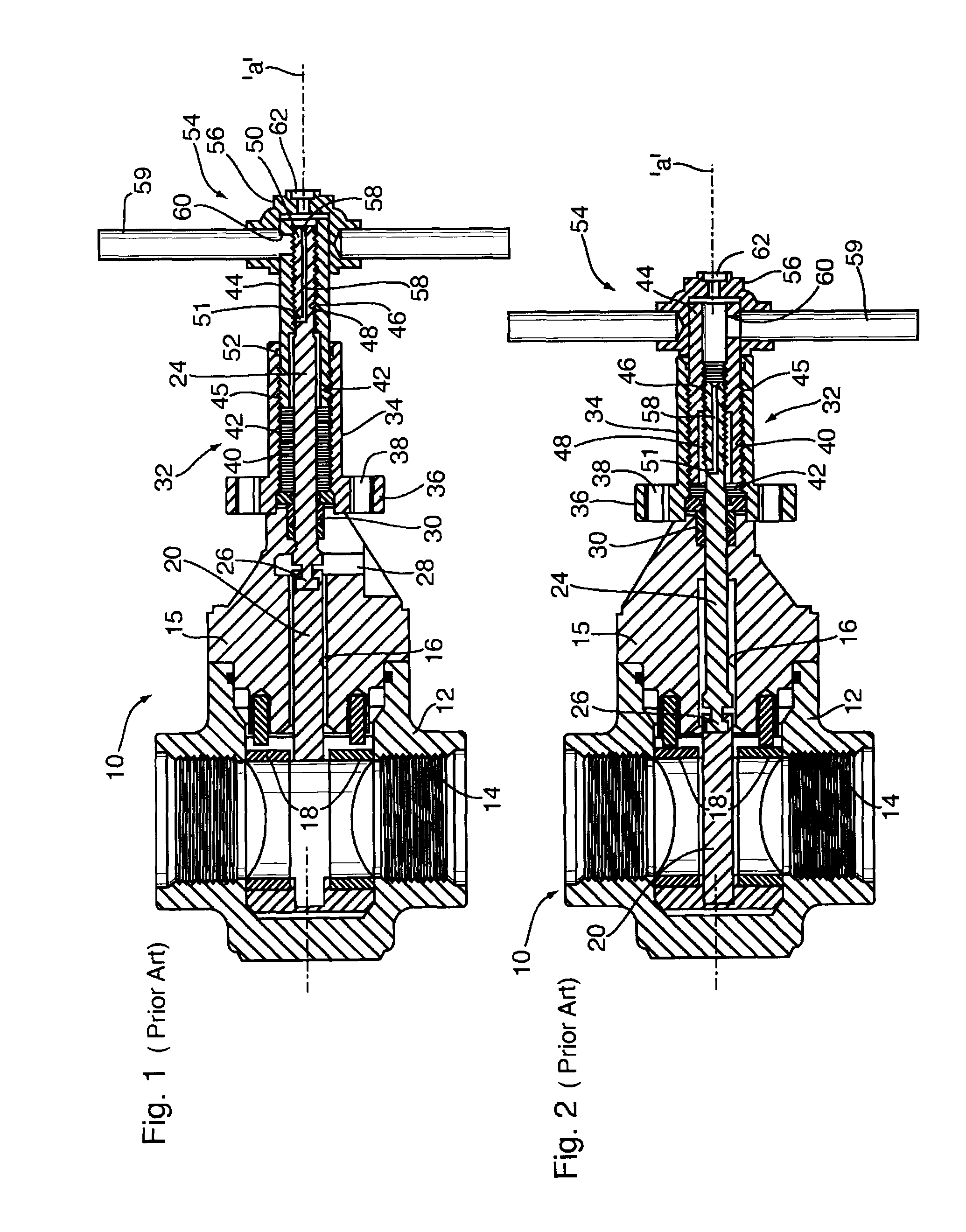
[0063]Referring to FIG. 1, FIG. 1 shows a typical so-called mud valve 10 of the prior art for use in regulating fluid flow through a transverse flow passage 14. FIG. 1 shows such prior art valve 10, namely a gate valve 10, in the open position while FIG. 2 shows the same valve 10 in the closed position.

[0064]Valves 10 of the type for which the tool of the present invention is particularly suited to be used in association with are typically used in water, oil, and gas lines, in wellheads, pipelines and manifolds, in abrasive drilling mud applications, in sour gas and crude oil, at pressures up to 15,000 psi (104 mPa) and temperature ranges of −40° F. to 400° F. Such valves 10 are typically employed in oilfield use to regulate flows from production casing of a drilled well, for which typical sizes are of 4½″ or 5½″ diameter.

[0065]Prior art valve 10 shown in FIGS. 1 & 2 is a typical gate valve used in aforementioned oil and gas well production manufactured under the trademark Demco® by...


PUM


Abstract

A tool for unseizing and / or lubricating a valve having a protruding valve stem on an exterior periphery. The tool possesses a hollow tubular member, having at one end thereof an open, hollow, cylindrical flexible member adapted to be placed over and contain therewithin a portion of the valve stem. A circumferential tightening member, encircling one end of the flexible member, is provided, to permit the flexible member to sealingly engage the valve stem about the outer periphery thereof when the flexible member is placed over the valve stem. The tool further possesses a fluid inlet port, situated along a length of the tubular member, in fluid communication with an interior of the tubular member, and a pressurized fluid inlet port likewise in fluid communication with the interior of the tool. A method for un-seizing and / or lubricating such valve, making use of the above tool, is further disclosed and claimed.

Description

CLAIM OF BENEFIT TO PRIORITY[0001]This application claims priority to Canadian Patent Application No. 2855789 filed Jul. 4, 2014 which is incorporated herein by reference in its entirety.FIELD OF THE INVENTION[0002]The present invention relates to well valves, and in particular to a tool for de-rusting and lubricating such valves, and a method of un-seizing valves which are seized.BACKGROUND OF THE INVENTION AND DESCRIPTION OF PRIOR ART[0003]Valves for regulating flow of liquids and gases in relatively large diameter pipes are typically gate valves and butterfly valves.[0004]Stem valves, which may include butterfly valves and gate valves having rising and non-rising stems, are widely used as oil field valves for production of oil and gas. Such valves are typically situated outdoors and are thus exposed to elements such as rain and snow, and further often regulate flow of oil and gas which may contain fluids [which in an unrefined state contain impurities such as sour gas (hydrogen s...

Claims


Application Information

Patent Timeline
Patent Type & Authority Patents(United States)
IPC IPC(8): E21B41/00E21B34/02F16K3/36F16N21/00F16N5/00B08B9/00
CPCE21B41/00B08B9/00E21B34/02F16K3/36F16N5/00F16N21/00Y10T137/043Y10T137/4259E21B21/10E21B34/06E21B43/12F16K29/00F16N11/00F16N21/02F16N2250/04
Inventor THISTLE, SCOTT
Owner PROGRESSIVE OILFIELD SERVICES
Why Eureka
Try Eureka