Eureka AIR delivers breakthrough ideas for toughest innovation challenges, trusted by R&D personnel around the world.

Antenna mounting for electronic devices

an electronic device and antenna technology, applied in the direction of instruments, portable computer details, electric apparatus casings/cabinets/drawers, etc., to achieve the effect of ensuring high radio wave sensitivity

Active Publication Date: 2009-07-16
LENOVO PC INT
View PDF19 Cites 41 Cited by
  • Summary
  • Abstract
  • Description
  • Claims
  • Application Information

AI Technical Summary

Benefits of technology

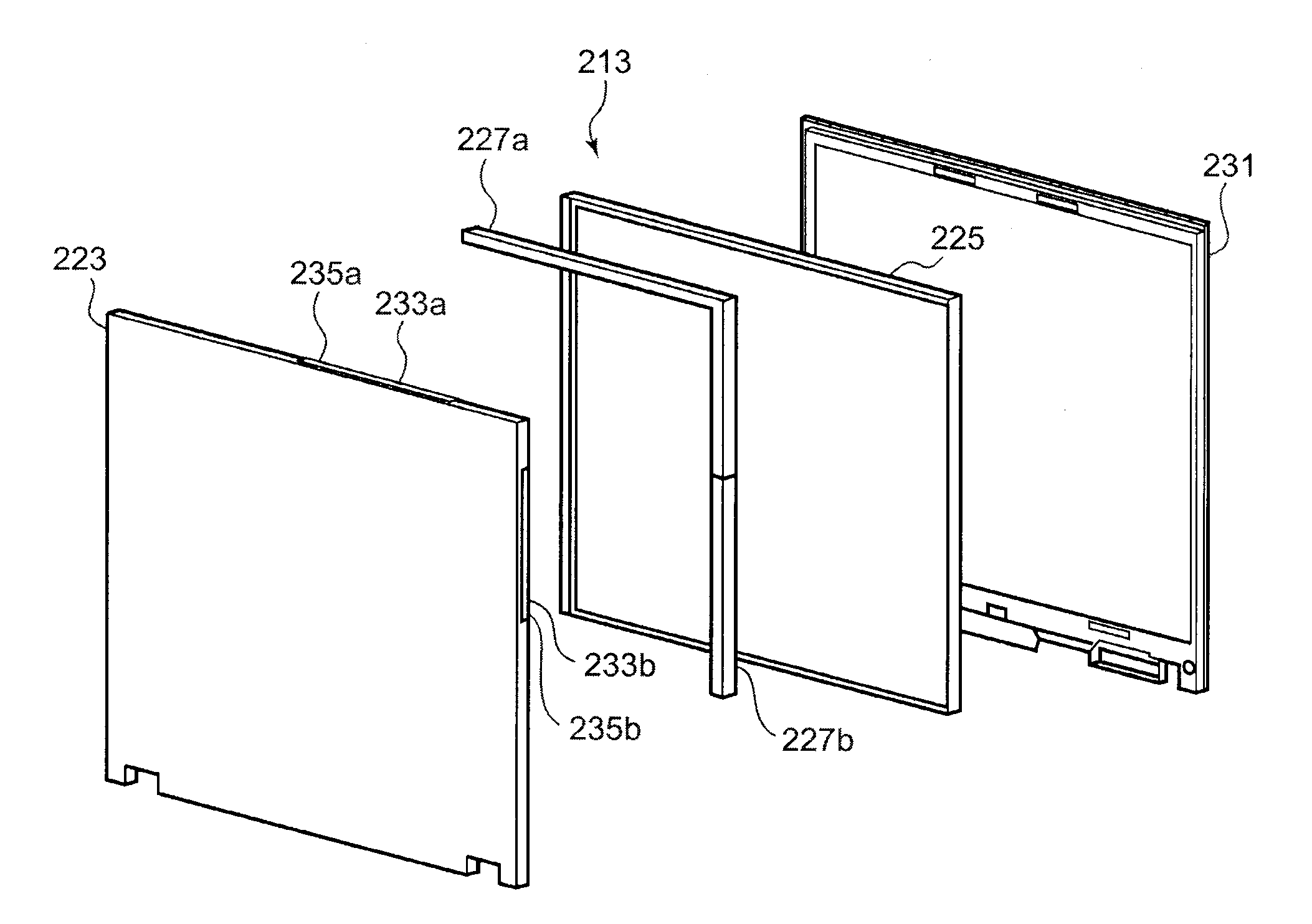
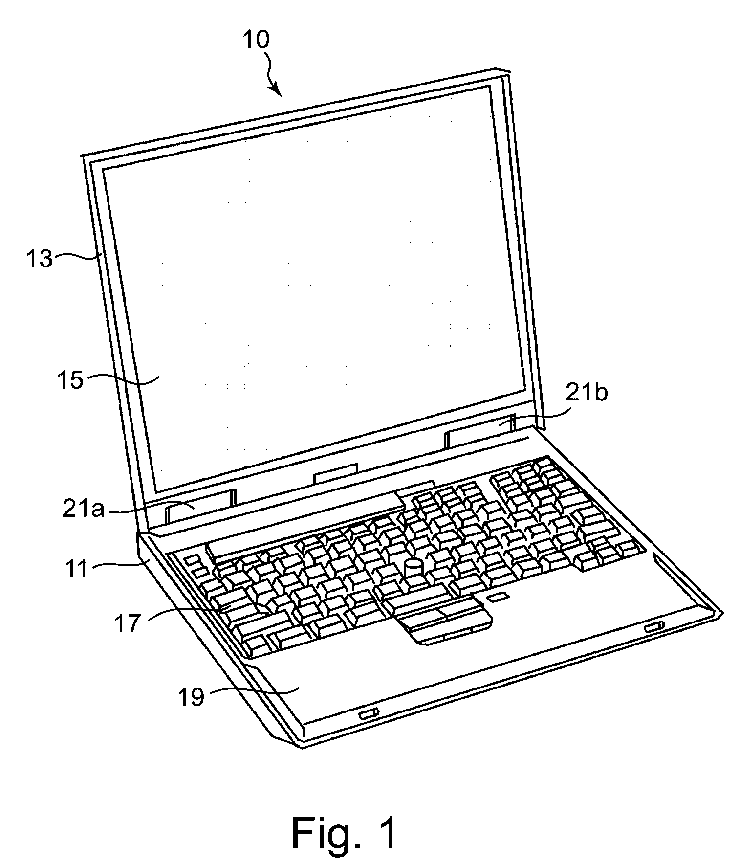
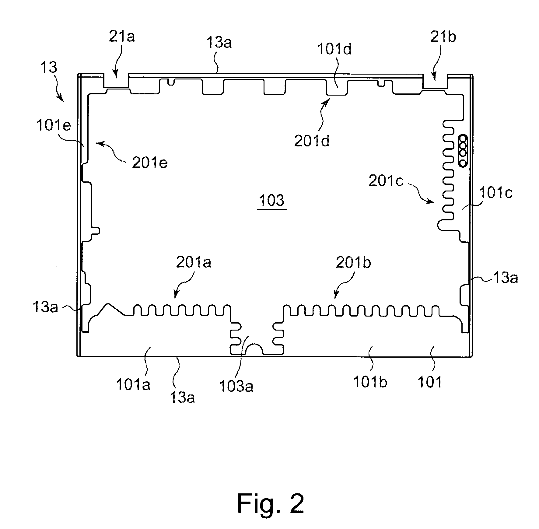
[0006]The present invention generally relates to an electronic apparatus which includes a display casing having a nonconductive resin region and a conductive resin region in a bottom surface thereof; a display module accommodated in the display casing; an antenna disposed in the nonconductive resin region; and a system casing accommodating a wireless module connected to the antenna. By disposing the antenna in the nonconductive resin region formed in the bottom surface of the display casing, it is possible to secure high radio wave sensitivity while preventing an antenna mounting portion from being exposed to the outside of the display casing.
[0007]In accordance with at least one presently preferred embodiment of the invention, there is broadly contemplated herein an electronic apparatus which achieves good antenna characteristics, while being thin in size and lightweight.

Problems solved by technology

In a metallic display casing, the cutout portions for securing the antenna sensitivity have weak points in terms of strength while posing designing problems; hence, a display casing having a new structure is demanded.

Method used


Image

  • Antenna mounting for electronic devices
  • Antenna mounting for electronic devices
  • Antenna mounting for electronic devices

Examples


Embodiment Construction

[0018]It will be readily understood that the components of the present invention, as generally described and illustrated in the figures herein, may be arranged and designed in a wide variety of different configurations. Thus, the following more detailed description of the presently preferred embodiments of the present invention, as represented in the figures, is not intended to limit the scope of the invention, as claimed, but is merely representative of selected embodiments of the invention.

[0019]Reference throughout this specification to “one embodiment” or “an embodiment” (or the like) means that a particular feature, structure, or characteristic described in connection with the embodiment is included in at least one embodiment of the present invention. Thus, appearances of the phrases “in one embodiment” or “in an embodiment” in various places throughout this specification are not necessarily all referring to the same embodiment.

[0020]Furthermore, the described features, structu...


PUM


Abstract

The invention broadly contemplates an electronic apparatus that provides improved antenna characteristics, while maintaining a thin size and light weight. The electronic apparatus of the present invention includes a display casing having a nonconductive resin region and a conductive resin region in a bottom surface thereof; a display module accommodated in the display casing; an antenna disposed in the nonconductive resin region; and a system casing accommodating a wireless module connected to the antenna. By disposing the antenna in the nonconductive resin region formed in the bottom surface of the display casing, it is possible to secure high radio wave sensitivity while preventing an antenna mounting portion from being exposed to the outside of the display casing. The casing structure of the electronic apparatus does not become thick because of butt joining even when the joint portions are in a projection area of an LCD module.

Description

CLAIM FOR PRIORITY[0001]This application claims priority from Japanese Patent Application No. 2008-004103, filed on Jan. 11, 2008, and which is fully incorporated by reference as if set forth herein.FIELD OF THE INVENTION[0002]The present invention generally relates to an electronic apparatus mounting an antenna thereon.BACKGROUND OF THE INVENTION[0003]In recent years, a portable computer such as a notebook type personal computer (hereinafter, referred to as “notebook PC”) has been standardized to have a radio communication antenna. The radio communication antenna is disposed on an upper surface or a side surface of a liquid crystal display so that the antenna exhibits the optimum sensitivity when users use the notebook PC. In order to cope with recent demands such as broad and multiple frequency bands, a high data transfer rate, or a diversity communication, the number of antennas mounted on a display-side casing of the notebook PC has been more and more increased.[0004]Japanese Pa...

Claims


Application Information

Patent Timeline
IPC IPC(8): H01Q1/24G06F1/16
CPCG06F1/1616G06F1/1698G06F1/1656G06F1/1637
Inventor JI, GANGOHTANI, TETSUYAMORINO, TAKAYUKIUCHINO, AKINORI
Owner LENOVO PC INT
Why Eureka
Eureka Blog
Learn More