Compact ink filter assembly

a filter assembly and inkjet printing technology, applied in printing and other directions, can solve the problems of high print speed, large ink supply flow rate, and high cost of ink supply

Inactive Publication Date: 2009-07-16
ZAMTEC +1
View PDF4 Cites 4 Cited by
  • Summary
  • Abstract
  • Description
  • Claims
  • Application Information

AI Technical Summary

Benefits of technology

[0014]The invention recognizes that the flow rate of ink through the filter membrane is greatest at the points proximate the inlet and remote from the outlet. Therefore the high flow rate areas of the membrane need to be adjacent larger volumes of supply ink. Conversely, the areas of low flowrate do not need to be adjacent large volumes of supply ink. By tapering the upstream portion of the chamber towards the outlet, no-flow or low-flow zones are minimized. If the low-flow areas of the membrane are adjacent large volumes of ink, this is essentially a dead volume of nearly stagnant ink. Therefore, the invention maintains the filter area while reducing the chamber volume for more compact design.

Problems solved by technology

Printing at these speeds consumes ink quickly and this gives rise to problems with supplying the printhead with enough ink.
Not only are the flow rates higher but distributing the ink along the entire length of a pagewidth printhead is more complex than feeding ink to a relatively small reciprocating printhead.
The high print speeds require a large ink supply flow rate.
Unfortunately, the smaller the filter pore size, the more it constricts the flow of ink.
However, large filter membranes are generally counter to compact design.

Method used


Image

  • Compact ink filter assembly
  • Compact ink filter assembly
  • Compact ink filter assembly

Examples


Embodiment Construction

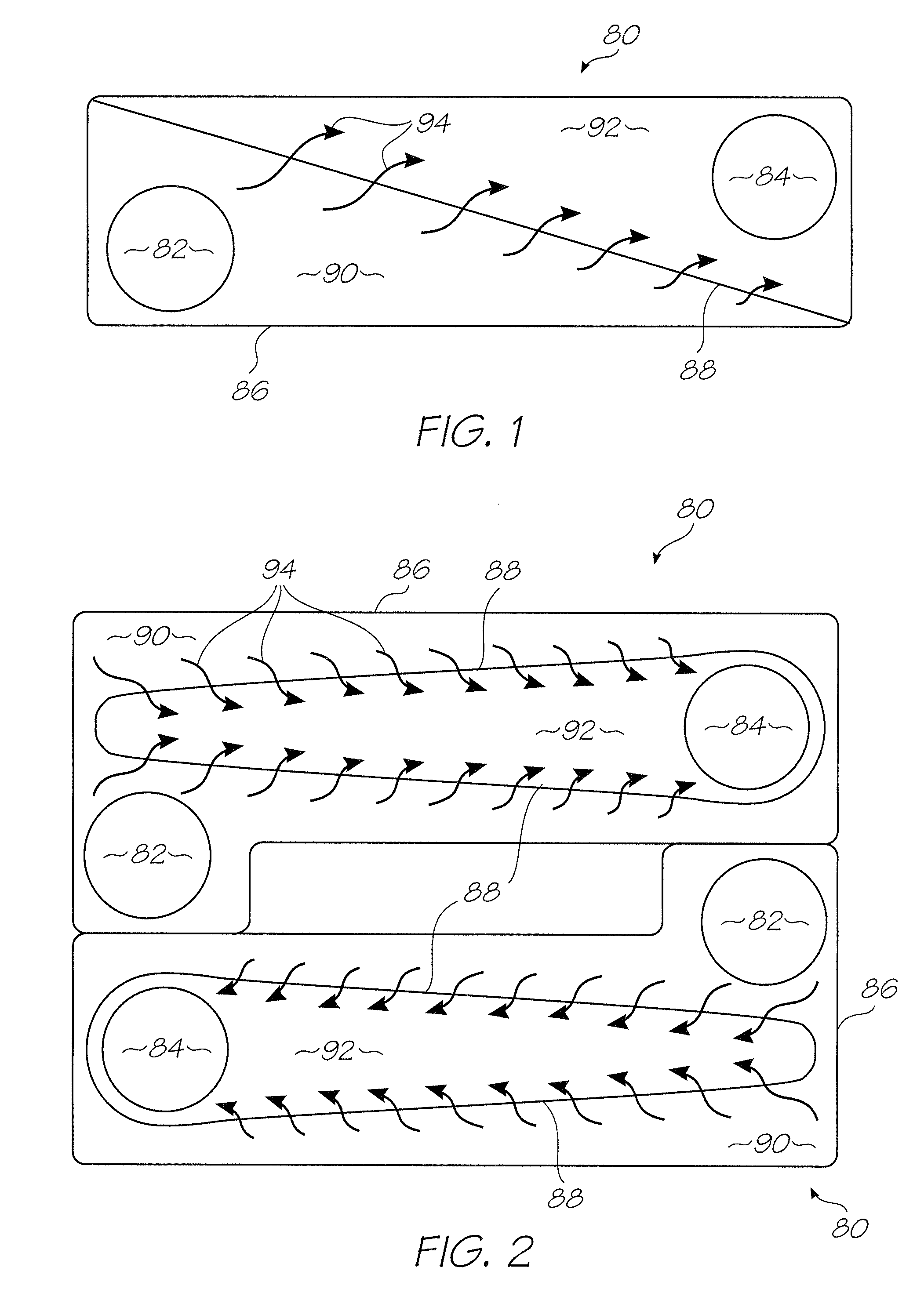
[0029]FIG. 1 is a sketch of a filter assembly 80 according to the invention is its basic form. The elongate chamber 86 houses an ink inlet 82 and an ink outlet 84 at either end. A filter membrane 88 extends diagonally across the chamber 86 to define an upstream portion 90 and a downstream portion 92. The ink flow through the membrane is schematically depicted by the arrows 94. The flow nearer the inlet 82 and remote from the outlet 84 is greatest, and conversely the flow remote from the inlet and near the outlet is less. Because of this, the upstream portion 90 of the chamber 86 is tapered towards the outlet 84. The areas of the membrane 88 that have the highest flow are supplied by a greater volume of ink in the relatively thick section of the upstream portion 90. The low flow areas of the membrane 88 are supplied with less ink from the thinner section of the upstream portion 90. In this way, the overall volume of the chamber can be minimized for a membrane of a particular area by ...


PUM


Abstract

A filter assembly for an inkjet printhead, that has an inlet for connection to an ink supply, an outlet for connection to an inkjet printhead, a filter membrane for filtering ink flowing from the inlet to the outlet, and a chamber to house the filter membrane. The filter membrane divides the chamber into an upstream portion for holding a quantity of the unfiltered ink, and a downstream portion for holding a quantity of the filtered ink. The upstream portion tapers towards the outlet and the downstream portion tapers towards the inlet.

Description

FIELD OF THE INVENTION[0001]The present invention relates to the field of inkjet printing and in particular, inkjet printers with pagewidth printheads.CO-PENDING APPLICATIONS[0002]The following applications have been filed by the Applicant simultaneously with the present application:RRE013USRRE014USRRE015USRRE016USRRE017USRRE018USRRE019USRRE020USRRE021USRRE022USRRE023USRRE024USRRE025USRRE026USRRE027USRRE028USRRE029USRRE030USRRE031USRRE032USRRE033USRRE034USRRE035USRRE036USRRE037USRRE038USRRE039USRRE040USRRE041USRRE042USRRE043USRRE044USRRE045USRRE046US[0003]The disclosures of these co-pending applications are incorporated herein by reference. The above applications have been identified by their filing docket number, which will be substituted with the corresponding application number, once assigned.CROSS REFERENCES[0004]The following patents or patent applications filed by the applicant or assignee of the present invention are hereby incorporated by cross-reference.62768506520631615890...

Claims


Application Information

Patent Timeline
Patent Type & Authority Applications(United States)
IPC IPC(8): B41J2/175
CPCB41J2/17563
Inventor BROWN, BRIAN ROBERTBERRY, NORMAN MICHEALMORGAN, JOHN DOUGLAS PETERHUDSON, MICHAEL JOHNNAKAZAWA, AKIRAMALLINSON, SAMUEL GEORGEJACKSON, GARY RAYMOND
Owner ZAMTEC
Why Eureka
Try Eureka