Check valve diaphragm micropump

a technology of diaphragm and check valve, which is applied in the direction of flexible member pumps, machines/engines, positive displacement liquid engines, etc., can solve the problems of unsuitability of rigid check valves and diaphragms, difficulty in transporting liquid that contains air or gases, and difficult to deliver gases with a comparatively high compressibility of such a micropump, so as to reduce the volume of the chamber

Active Publication Date: 2013-07-02
WAYNE STATE UNIV
View PDF11 Cites 1 Cited by
  • Summary
  • Abstract
  • Description
  • Claims
  • Application Information

AI Technical Summary

Benefits of technology

[0026]In still another example, structuring the cavity includes making the part of the cavity that spans the diaphragm shallower than the other part that spans the inlet and outlet sections to reduce the chamber volume.

Problems solved by technology

This makes it difficult for such a micropump to deliver gases that have a comparatively high compressibility.
It is also difficult to transport liquid that contains air or gases, since the gas pockets accumulate in the chamber and have high compressibility.
For check valve diaphragm micropumps, rigid check valves and diaphragms are unsuitable, since the resistance of the valve is greater than the pressure difference created by the diaphragm actuation mechanism.
However, overly flexible check valves and diaphragms are also unsuitable, since leakage would be high and the dynamic response of the micropump would be low, precluding an expected linear working range.

Method used


Image

  • Check valve diaphragm micropump
  • Check valve diaphragm micropump
  • Check valve diaphragm micropump

Examples


Embodiment Construction

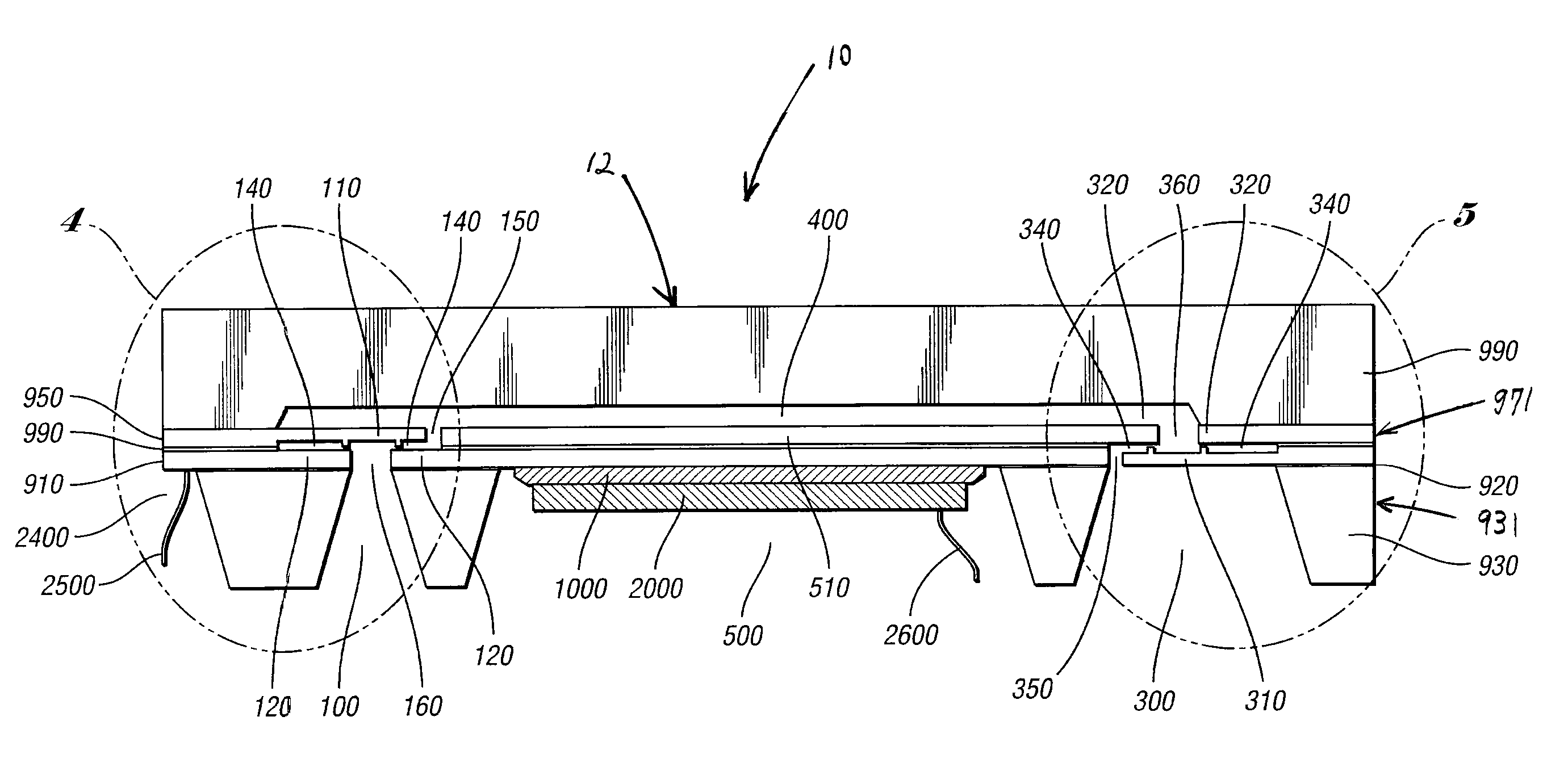
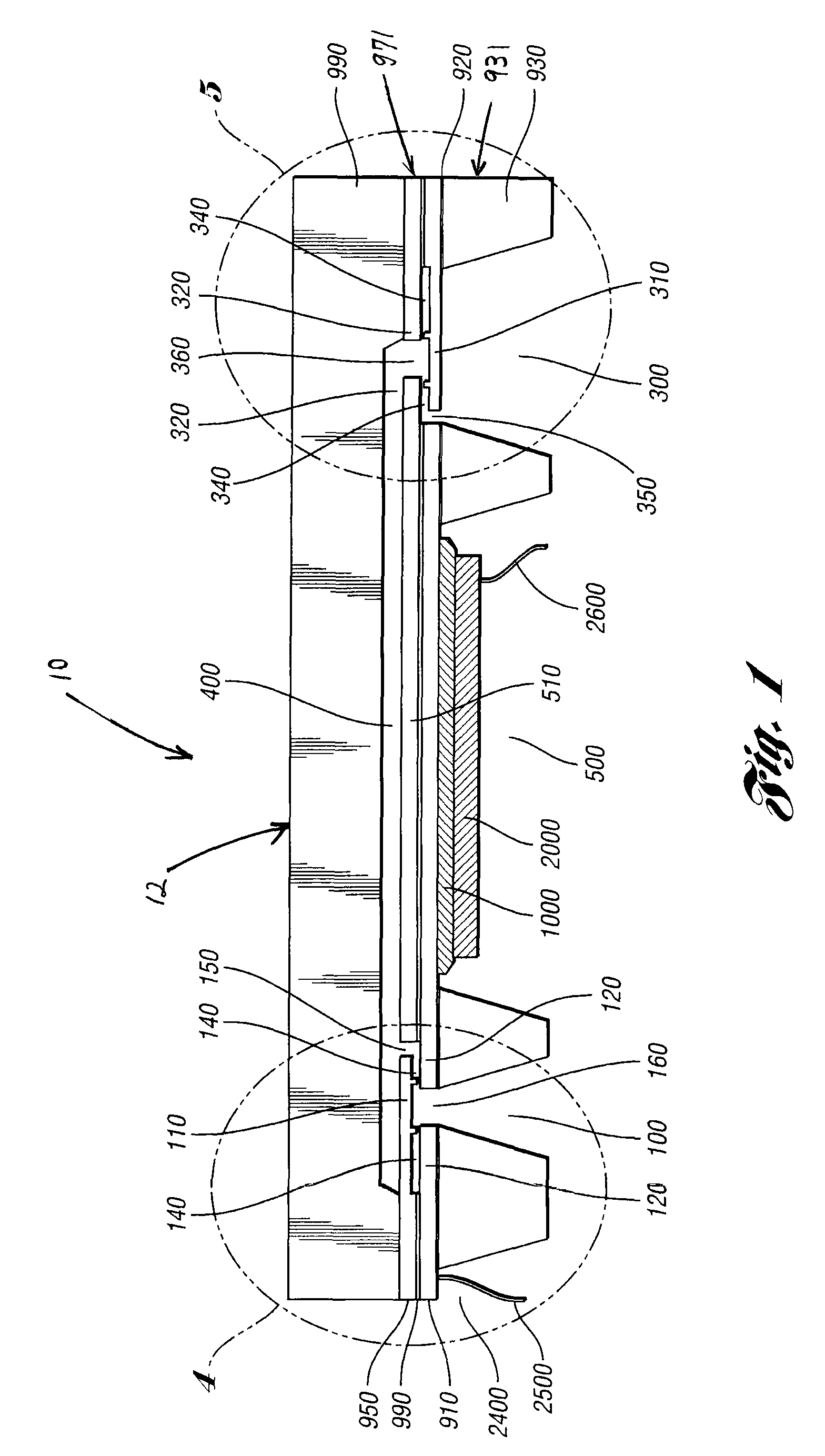
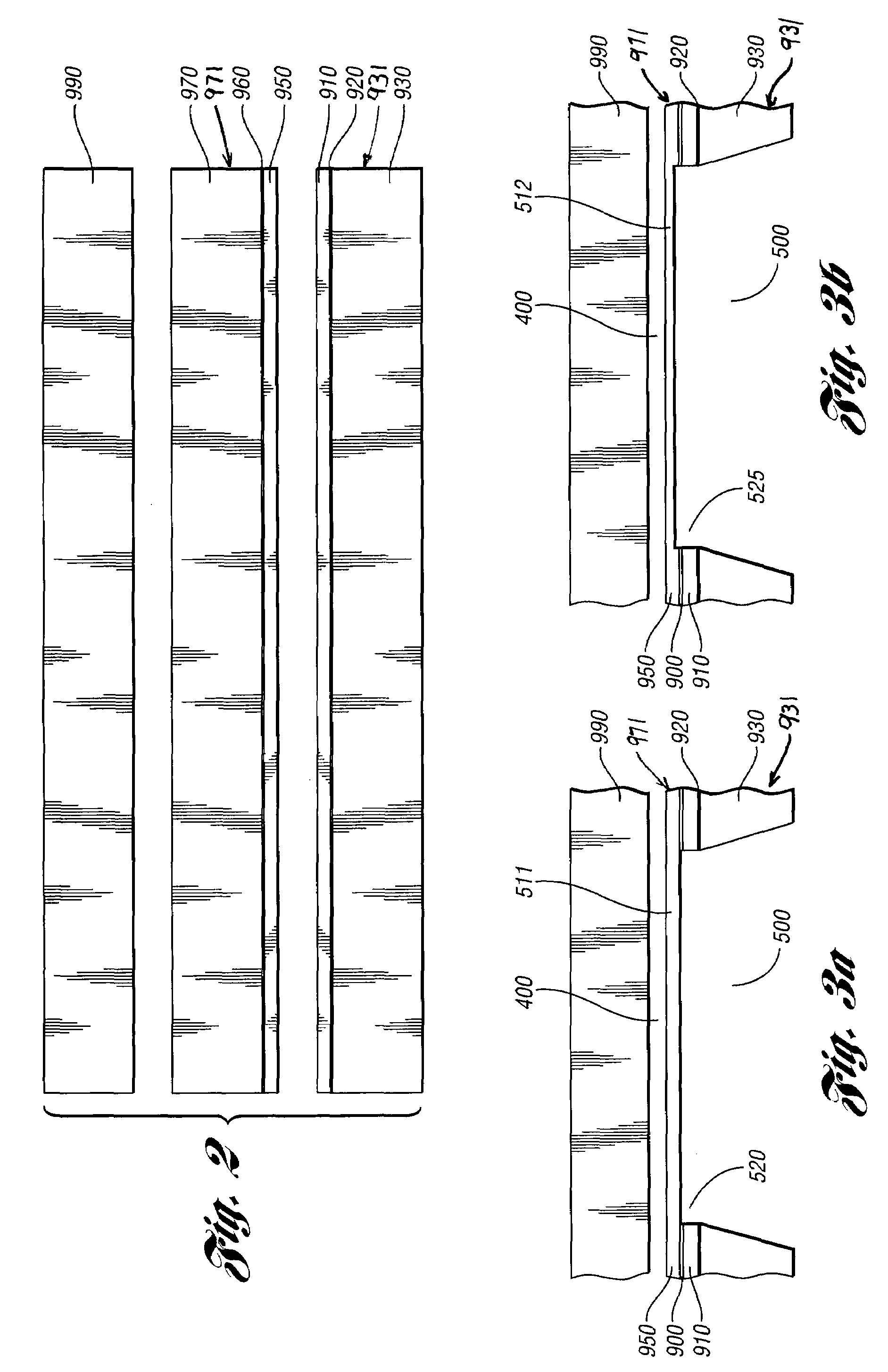
[0043]The performance of a micropump is mainly affected by the material properties, horizontal dimensions, and vertical dimensions. The horizontal dimensions are determined by any appropriate means including, but not limited to, photolithography. The vertical dimensions are controlled within an acceptable error range to make a micropump having a desired performance range.

[0044]The present invention takes advantage of advanced microfabrication technologies, such as photolithography, oxidation, deposition, etching, and bonding. Commercially available wafers, Silicon-on-Insulator (SOI) or Epitaxial™ wafers, are used to construct the micropumps. Core components of the micropump, including the diaphragm, the inlet and outlet valves are made within well-defined device layers of the wafers by, for example, a technique called bonding and etching back. These wafers have buried within a layer resistant to etching. Therefore, accurate deep etching may be achieved by automatic etching methods w...


PUM

PropertyMeasurementUnit
thicknessaaaaaaaaaa
depthaaaaaaaaaa
compression ratioaaaaaaaaaa

Abstract

A micropump device including a first wafer and a second wafer attached to the first wafer. The first and second wafers are configured to define a chamber therebetween having a predetermined volume. A third wafer is attached to the second wafer to define an inlet section and an outlet section in fluid communication with the chamber. At least one of the second and third wafers are formed to define a moveable diaphragm configured to change the predetermined volume of the chamber for pumping a fluid between the inlet section and the outlet section.

Description

CROSS REFERENCE TO RELATED APPLICATIONS[0001]This patent application claims the benefit of PCT / US2007 / 008280, filed Mar. 30, 2007, and U.S. provisional patent application 60 / 787,332, filed Mar. 30, 2006, entitled “CHECK VALVE DIAPHRAGM MICROPUMP,” the entire contents of which are incorporated herein by reference.FEDERALLY SPONSORED RESEARCH AND DEVELOPMENT[0002]This invention was made with government support under Contract No. ANI-0086020 awarded by the U.S. National Science Foundation. The U.S. government may retain certain rights to the invention.BACKGROUND OF THE INVENTION[0003]There is relatively high demand for microfluidic systems due to their needed small size, easy portability, and low cost for research, civil, and even some military applications. One core device of a microfluidic system is a micropump. In the past decades, researchers have proposed and developed various micromachining micropump prototypes. Commercially available micropumps made with batch fabrication techni...

Claims


Application Information

Patent Timeline
Patent Type & Authority Patents(United States)
IPC IPC(8): F04B17/00
CPCA61M5/14224A61M2205/0244A61M2205/0294F04B43/046Y10T29/49229Y10T29/49236Y10T137/2191Y10T137/2213Y10T137/2218
Inventor KANG, JIANKEAUNER, GREGORY W.
Owner WAYNE STATE UNIV
Why Eureka
Try Eureka