Liquid container
a liquid container and liquid technology, applied in printing and other directions, can solve the problems of large deflection range, increased shock absorption material thickness, and pinched between them, and achieve the effect of high reliability and cost increas
- Summary
- Abstract
- Description
- Claims
- Application Information
AI Technical Summary
Benefits of technology
Problems solved by technology
Method used
Image
Examples
first embodiment
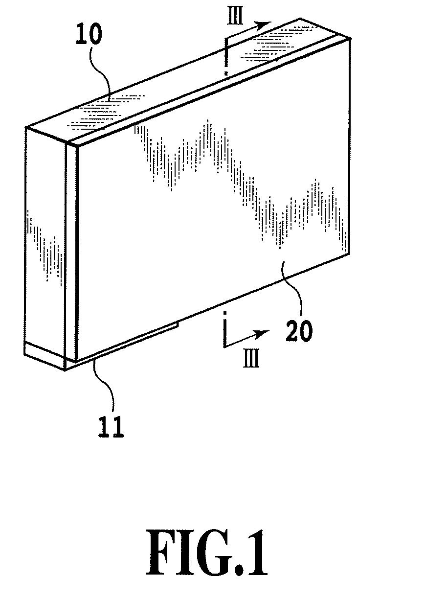
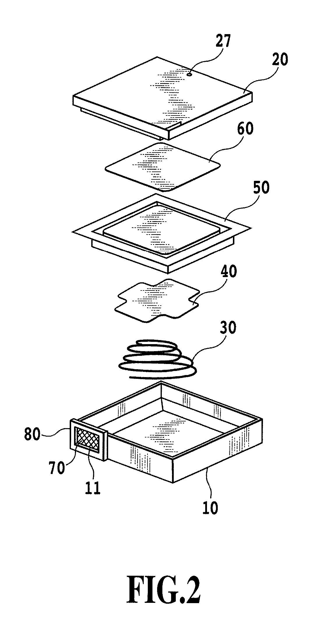
[0067]FIG. 1 to FIG. 11 are drawings to explain the first embodiment of this invention. FIG. 1 is an outline perspective view of an ink tank in the first embodiment, and FIG. 2 is an exploded perspective view of the ink tank.
[0068]The ink tank of this embodiment, as shown in an outline perspective view of FIG. 1, comprises a case 10 and a cover member 20. An ink accommodation space is formed in the ink tank as a liquid accommodation space (liquid accommodation chamber), as described later. At its bottom the case 10 has an ink supply port 11 from which to supply ink from an ink accommodation space to a print head not shown.
[0069]As shown in FIG. 2, the ink tank has the case 10, a spring member 30, a plate member 40, a flexible film 50, a shock absorbing sheet 60, the cover member 20, a meniscus forming member 70 and a holding plate 80. The case 10 may, for example, be formed of a resin material such as polypropylene. Held at its circumferential part by the holding plate 80, the menis...
second embodiment
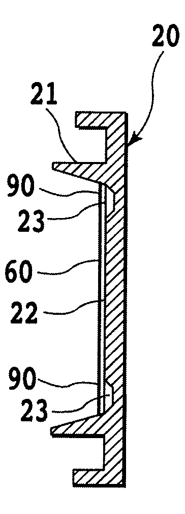
[0095]Next, the construction of an ink tank according to a second embodiment of this invention will be explained by referring to FIG. 12. FIG. 12 is a front view of a cover member 20 and a shock absorbing sheet 60, combined together to form shock absorbing portions 90.
[0096]The ink tank of this embodiment is so constructed as to be able to prevent damages to the film 50 if the ink tank falls with its flat outer surface landing on the ground. That is, the ink tank can prevent damages to the film 50 even if the film 50 has low stiffness and is liable to damage and if not only the corner portions 41A but also the edge portions 42A of the plate member 40 strike the inner surface 22 of the cover member 20.
[0097]The recessed portions 23 of the cover member 20 in this embodiment are wider than those of the first embodiment. That is, the size of the recessed portions 23 is so set that, if the plate member 40 moves in an allowable range inside the rib 21, the recessed portions23 always oppos...
third embodiment
[0102]Next, the construction of an ink tank according to a third embodiment of this invention will be explained by referring to FIG. 14A, FIG. 14B, FIG. 15 and FIG. 24A-24C. FIG. 14A is a front view showing a recessed portion 23 of the cover member 20 and a shock absorbing sheet 60, combined together to form a shock absorbing portion90. FIG. 14B is a cross-sectional view taken along the line XIVB-XIVB of FIG. 14A. FIG. 15 is a cross-sectional view of the ink tank of this embodiment taken along the line III-III of FIG. 1. FIG. 24A is a perspective view of the cover member of FIG. 14A. FIG. 24B is an enlarged view of a portion XXIVB of FIG. 24A. FIG. 24C is a cross-sectional view taken along the line XXIVC-XXIVC of FIG. 24A.
[0103]As described above, when the ink tank falls and hits the ground, the plate member 40 moves in the gravity direction and at the same time tilts to move its impacting side toward the cover member 20. At this time, the plate member 40 may first hit the rib 21 of...
PUM
 Abstract
Description
Claims
Application Information
 - R&D
- Intellectual Property
- Life Sciences
- Materials
- Tech Scout
- Unparalleled Data Quality
- Higher Quality Content
- 60% Fewer Hallucinations
Browse by: Latest US Patents, China's latest patents, Technical Efficacy Thesaurus, Application Domain, Technology Topic, Popular Technical Reports.
© 2025 PatSnap. All rights reserved.Legal|Privacy policy|Modern Slavery Act Transparency Statement|Sitemap|About US| Contact US: help@patsnap.com


