Insect trap

a technology for insects and traps, applied in the field of insect traps, can solve the problems of unfavorable insect capture and capture, poor quality of insects, and difficult packaging, and achieve the effects of convenient packaging, deployment and disposal, and cheap manufacturing

Inactive Publication Date: 2009-07-23
GAITHER BRUCE
View PDF21 Cites 37 Cited by
  • Summary
  • Abstract
  • Description
  • Claims
  • Application Information

AI Technical Summary

Benefits of technology

[0005]The inventive solution presented here is a insect trapping device comprising a truncated, tapered, hollow body such as a truncated cone or pyramid. It incorporates a nondrying glue such as that used in flypaper that substantially covers its interior surface. It optionally accommodates user-supplied attractants, such as dung for houseflies or overripe fruit for fruit flies. It may be packaged by folding, stacking, or lying flat, depending upon the design details. The invention therefore overcomes the limitations of the prior art as it is easy to package, deploy and dispose of, may be manufactured cheaply, accommodates the insect's user-supplied natural attractants, hides the captured insects from public view when in use, and may be applied in a variety of different applications—from use in an open field or inside a barn to sitting on a kitchen countertop.

Problems solved by technology

However all these products have one or more limitations, and their commercial success is extremely limited.
They may be messy to deploy, unpleasant to look at, expensive to build, and have limited marketability because of their restricted use.

Method used


Image

  • Insect trap
  • Insect trap
  • Insect trap

Examples


embodiment one

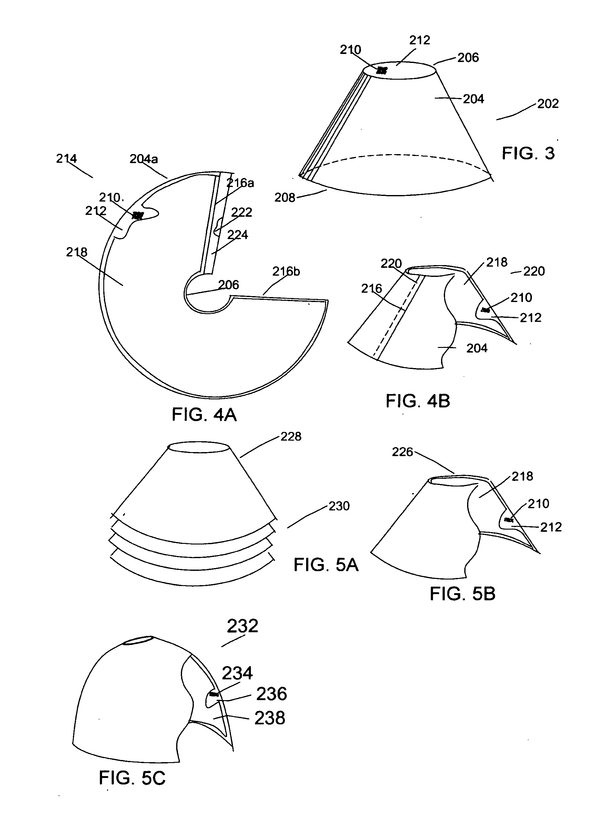
[0025]FIG. 3 displays the first embodiment in its deployed configuration 202. It consists of a hollow, substantially rigid, truncated cone 204 with a small opening 206 at the narrow end of the tapered cone and a second larger opening 208 at the wider end of the cone. Its interior surface 212 is substantially coated with sticky.

[0026]FIG. 4A illustrates the first embodiment in a packaged configuration as it would be stored or displayed in a merchant's store. FIG. 4B shows the ready to deploy configuration of the first embodiment constructed by reconfiguring the packaged configuration into a conical shape.

[0027]Referring now to FIGS. 4A and 4B, the ready to deploy configuration 220 of the first embodiment, constructed from the packaged configuration 214, consists of the truncated cone 204, with sticky 210 substantially covering the interior surface 212 of the truncated cone 204. The sticky is covered by a removable covering 218. The truncated cone 204 is constructed from a flat materi...

embodiment two

[0028]FIGS. 5A and 5B illustrate the construction of a second embodiment in its packaged configuration and its ready to deploy configuration. Referring to FIG. 5B, the ready to deploy 226 configuration of the second embodiment has the same structure of the ready to deploy configuration of FIG. 4B, but with one difference. Instead of constructing the truncated cone 204 from an annulus segment 204a, the truncated cone 228 is already manufactured as a hollow body. The truncated cone 226 has sticky 210 applied to its interior 212. The covering 218 is made from an annulus segment 218 as in FIG. 4A. FIG. 5A shows how this embodiment is packaged. Referring to FIG. 5A, several or many units of the second embodiment 228 are stacked one on top of the other 230. This will display nicely on a merchants shelf and will pack nicely for shipping. FIG. 5B show a ready to deploy unit. It is essentially the same as shown in FIG. 4B.

embodiment three

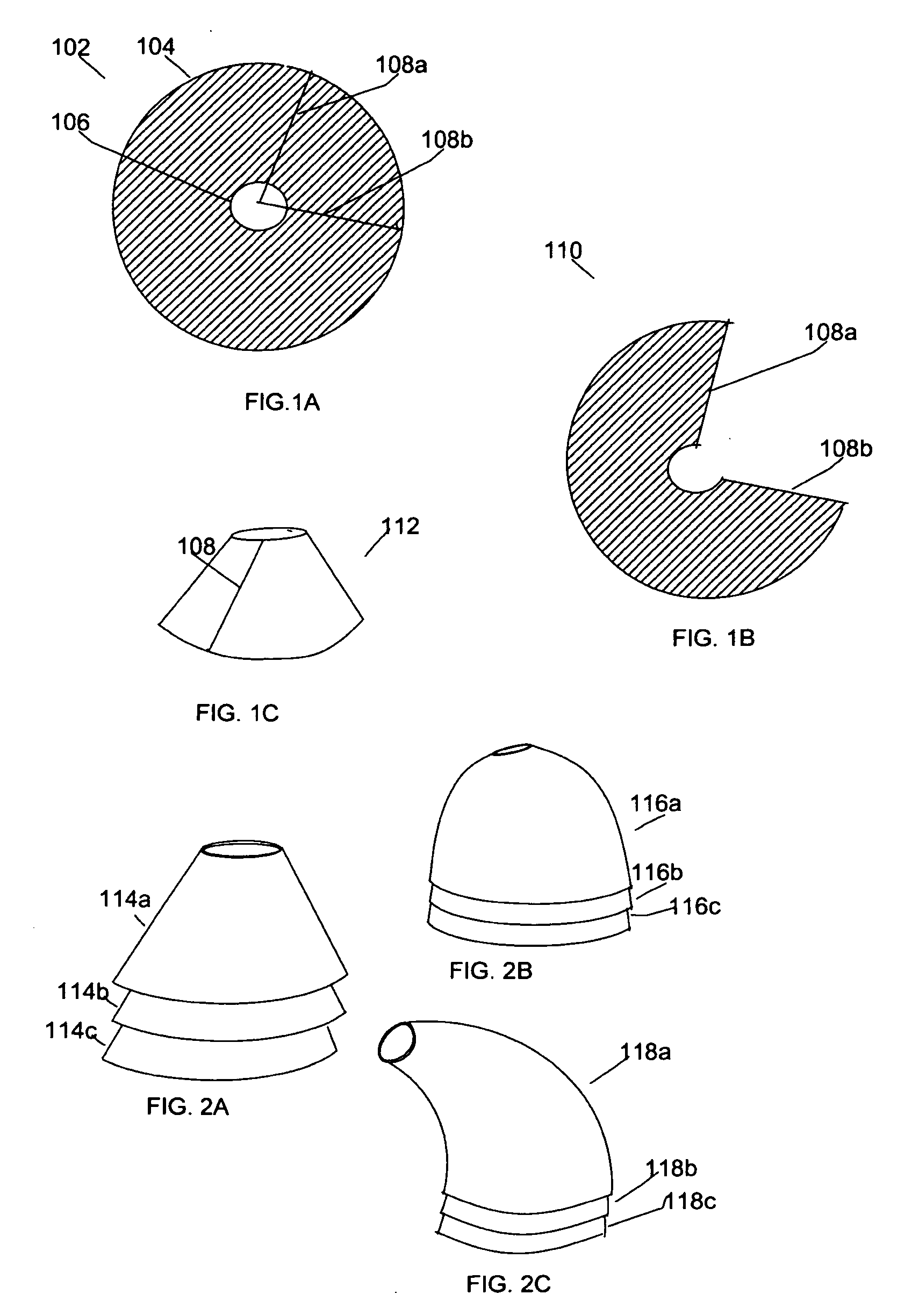
[0029]FIG. 5C illustrates a design for a third embodiment, the beehive design, that is in its ready to deploy configuration. The single beehive 232 has sticky 234 substantially covering its interior 236 (not shown in the figure). It also has a removable covering cover for the sticky 238. As in the second embodiment, the third embodiment is stackable as shown in FIG. 2B.

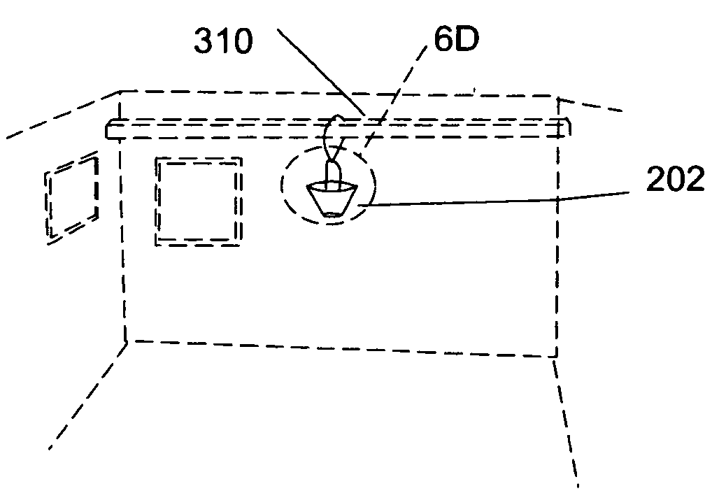
[0030]The size of the various embodiments may vary widely depending on their intended use. FIG. 6A shows the first embodiment of the insect trap used in a field where large animals, such as cows or horses, graze. A pile of animal dung 302 lies on the ground and attracts flies. The insect trap is placed over the dung, and will trap the flies as they are attracted to the dung. In this application the cone is relatively large, the height typically about 40.5 cm (16 in). A “muck bucket” filled with manure or other substances that attracts flies found in a field may also be used.

[0031]FIG. 6B shows a much smaller version o...


PUM


Abstract

The invention is a insect trapping device comprising a truncated, tapered hollow body such as a truncated cone or pyramid having a nondrying glue substantially covering its interior surface. The glue has a removable covering that protects it when it is in its package or ready to deploy configuration. It may be placed on a horizontal surface with the large opening facing down or hung in an overhead position with the large opening facing up. The device may be sized for different applications: a large version placed over dung in a field will capture house flies, while a smaller version put on a countertop using overripe fruit as an attractant will capture fruit flies. Various embodiments are presented that allow the embodiment to be folded, stacked, or flattened for storage. The invention traps members of the insecta class (e.g. flies), members of the arachnid class (e.g. spiders) and other arthropods.

Description

CROSS-REFERENCE TO RELATED APPLICATIONS [0001]This application claims the benefit of the U.S. Provisional Patent Application No 61 / 022,951 filed Jan. 23, 2008 by the present inventor. This provisional patent application is incorporated herein by reference.FIELD OF THE INVENTION[0002]This invention relates to devices that trap insects; more specifically to devices that trap insects using a nondrying glue such as found on flypaper and glue boards.BACKGROUND OF THE INVENTION[0003]There are many types of insect traps designed to capture and kill insects, both flying and crawling. A very common type uses a nondrying glue that the insect sticks to upon contact. Traps using nondrying glues are a mature product area. Coiled flypaper ribbons, flypaper boards and sheets using nondrying glue are currently widely available. There are also numerous patents addressing more elaborate products using nondrying glue; they often incorporate additional features such as lights to attract the insects, co...

Claims


Application Information

Patent Timeline
Patent Type & Authority Applications(United States)
IPC IPC(8): A01M1/14
CPCA01M1/14
Inventor HARRIS, SCOTT K.
Owner GAITHER BRUCE
Why Eureka
Try Eureka