Flow operated orienter

a flow-operated, orienter technology, applied in the direction of directional drilling, interengaging clutches, borehole/well accessories, etc., can solve the problems of inability to drill an effective straight wellbore section, inability to rotate the bha, and inability to effectively drill a straight wellbore section

Inactive Publication Date: 2009-07-23
WEATHERFORD TECH HLDG LLC
View PDF98 Cites 31 Cited by
  • Summary
  • Abstract
  • Description
  • Claims
  • Application Information

AI Technical Summary

Problems solved by technology

When drilling with coiled tubing, neither rotary drilling nor rotational orientation of the BHA can be accomplished without the addition to the BHA of a special rotating device to orient the BHA since coiled tubing cannot be rotated in the wellbore f

Method used


Image

  • Flow operated orienter
  • Flow operated orienter
  • Flow operated orienter

Examples


Embodiment Construction

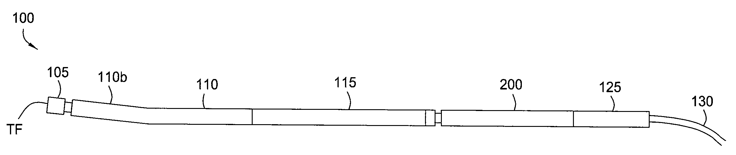
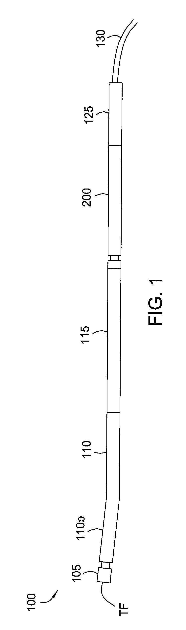
[0020]FIG. 1 is a diagram of a coiled tubing Bottom Hole Assembly (BHA) 100, according to one embodiment of the present invention. The coiled tubing BHA 100 may include: a drill bit 105, a first mud motor (or bit motor) 110, measurement while drilling (MWD) module 115, orienter 200, and an adapter 125. The bit motor 110 may harness fluid energy from drilling fluid by channeling it between a profiled rotor and stator, thereby imparting the energy into rotational motion of the rotor. The bit motor 110 may be a positive displacement motor (PDM), such as a Moineau motor, or a turbomachine, such as a centrifugal, axial flow, or mixed flow motor.

[0021]The drill bit 105 may be longitudinally and rotationally coupled to the rotor of the bit motor 110, such as by a threaded connection. The stator of the bit motor 110 may be disposed in and longitudinally and rotationally coupled to a housing of the bit motor 110. The rotor of the bit motor 110 may be disposed in the housing of the bit motor ...


PUM


Abstract

Embodiments of the present invention generally relate to a flow operated orienter. In one embodiment, a bottom hole assembly (BHA) for use in drilling a wellbore includes: a first mud motor having a stator and a rotor; a second mud motor having stator and a rotor; a drill bit rotationally coupled to the second rotor and having a tool face and a longitudinal axis inclined relative to a longitudinal axis of the first mud motor; and a clutch. The clutch is operable to: rotationally couple the second stator to the first stator in a first mode at a first orientation of the tool face, rotationally couple the first rotor to the second stator in a second mode, change the first orientation to a second orientation by a predetermined increment, orient the tool face at the second orientation in an orienting mode, and shift among the modes in response a change in flow rate of a fluid injected through the orienter and/or a change in weight exerted on the drill bit.

Description

CROSS-REFERENCE TO RELATED APPLICATIONS[0001]This application claims benefit of U.S. Provisional Patent Application No. 61 / 011,397 (Atty. Dock. No. WEAT / 0863L), filed Jan. 17, 2008, which is hereby incorporated by reference in its entirety.BACKGROUND OF THE INVENTION[0002]1. Field of the Invention[0003]Embodiments of the present invention generally relate to a flow operated orienter.[0004]2. Description of the Related Art[0005]Conventional directional drilling with a drillstring of jointed pipe is accomplished through use of a Bottom Hole Assembly (BHA) including a bent sub (typically one-half to three degrees), a drilling or mud motor, and directional Measurement While Drilling (MWD) tool in the following fashion. To drill a curved wellbore section, the drillstring is held rotationally fixed at the surface and the drilling motor will drill a curved wellbore in the direction or orientation of the bent sub. This is termed slide drilling because the entire drillstring slides along the...

Claims


Application Information

Patent Timeline
IPC IPC(8): E21B7/08F16D25/00E21B4/16E21B7/04E21B7/06
CPCE21B7/067E21B23/04E21B23/006E21B7/068E21B7/04E21B7/06
Inventor GURJAR, RISHINEUMANN, OMAR
Owner WEATHERFORD TECH HLDG LLC
Why Eureka
Try Eureka