Structure for mounting power supply apparatus on vehicle

a technology for power supply equipment and vehicle body, which is applied in the direction of cell components, cell component details, electrochemical generators, etc., can solve the problems of malfunction or noise of electronics provided at the instrument panel, and achieve the effect of ensuring enough legroom for the rear sea

Inactive Publication Date: 2009-07-23
TOYOTA JIDOSHA KK
View PDF43 Cites 81 Cited by
  • Summary
  • Abstract
  • Description
  • Claims
  • Application Information

AI Technical Summary

Benefits of technology

[0007]According to the structure for mounting a power supply apparatus on a vehicle configured in the above-described manner, the instrument panel is shielded by the power supply portion from the electrical component. Therefore, arrival of an electromagnetic wave emitted from the electrical component at the electronics provided at the instrument panel can be suppressed. As a result, the electronics can be appropriately protected from the electromagnetic wave.
[0008]Preferably, the electronics are provided at a position higher than the electrical component. According to the structure for mounting a power supply apparatus on a vehicle configured in the above-described manner, an electromagnetic wave from the upper side of the electrical component will readily reach the electronics. Therefore, the upper side of the electrical component is covered with the power supply portion. Thus, arrival of the electromagnetic wave at the electronics can be prevented more effectively.
[0011]Preferably, the structure for mounting a power supply apparatus on a vehicle further includes a metallic floor panel provided on a floor inside the vehicle compartment. The first power supply portion is installed on the floor panel. The electrical component has three sides surrounded by the first power supply portion, the second power supply portion and the floor panel. According to the structure for mounting a power supply apparatus on a vehicle configured in the above-described manner, arrival of an electromagnetic wave emitted from the electrical component at the electronics provided at the instrument panel can be suppressed more effectively.
[0014]According to the structure for mounting a power supply apparatus on a vehicle configured in the above-described manner, the electrical equipment is installed on a path of the first exhaust passage through which the cooling air is discharged from the first power supply portion having the smaller number of the stacked power supply cells. As a result, a difference between a pressure loss on the path of the cooling air flowing through the first power supply portion and the first exhaust passage in turn and a pressure loss on the path of the cooling air flowing through the second power supply portion and the second exhaust passage in turn can be lessened.
[0016]As described above, according to the present invention, there can be provided a structure for mounting a power supply apparatus on a vehicle where electronics provided at an instrument panel are appropriately protected from an electromagnetic wave.

Problems solved by technology

Therefore, an electromagnetic wave emitted from the electrical components might cause a malfunction or noise of electronics provided at the instrument panel.

Method used


Image

  • Structure for mounting power supply apparatus on vehicle
  • Structure for mounting power supply apparatus on vehicle
  • Structure for mounting power supply apparatus on vehicle

Examples


case 51

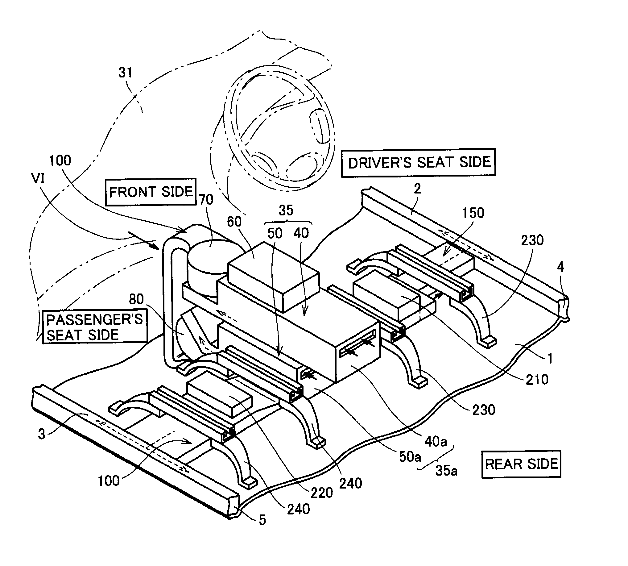
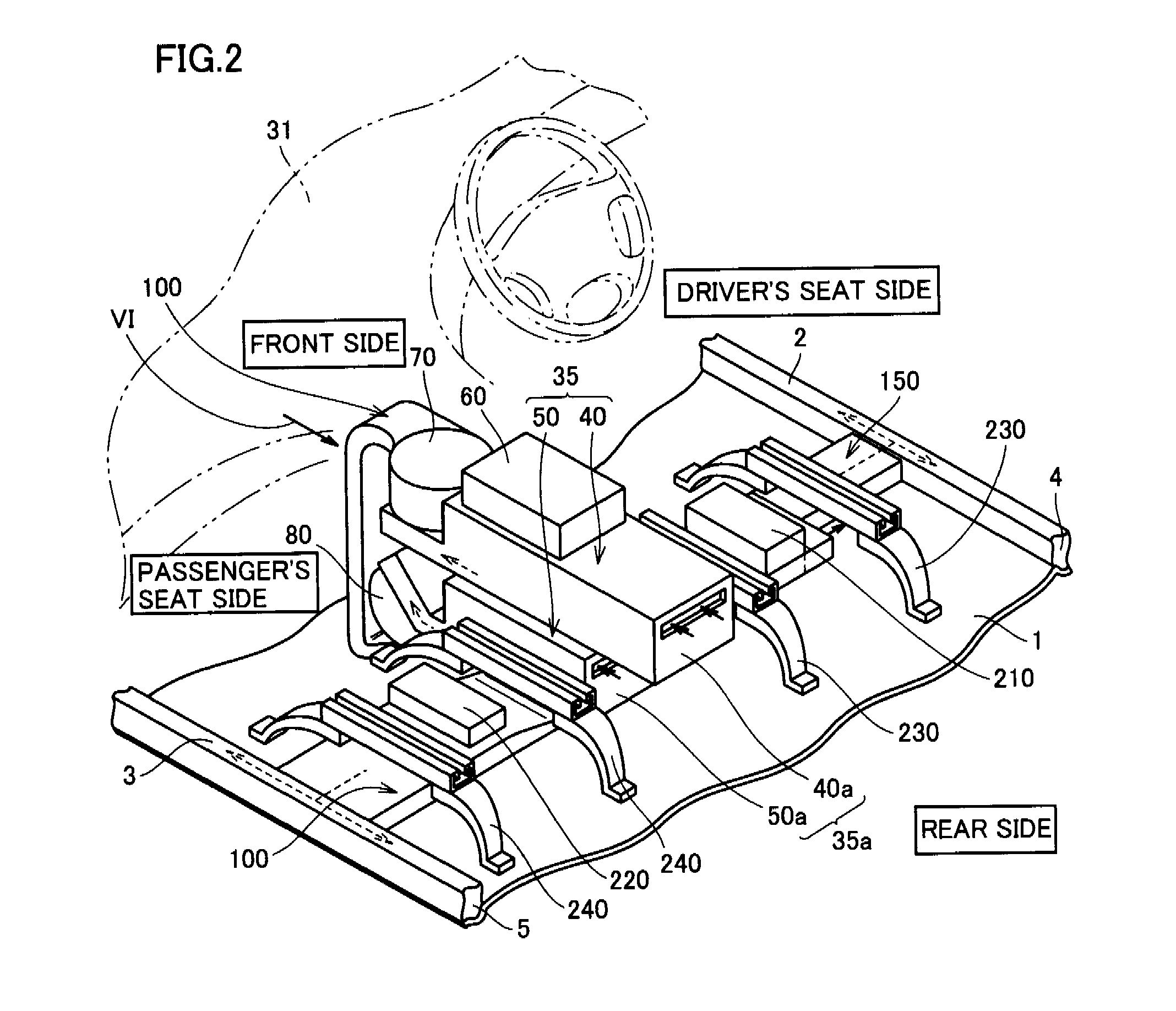
[0035]Battery case 51 is made of metal. Battery case 51 is formed of, for example, a galvanized steel plate in order to ensure strength. Battery case 51 includes a covering portion 52 and an extended portion 53. Covering portion 52 is formed so as to surround batteries 54. Covering portion 52 is formed in a substantially rectangular parallelepiped shape having a long side direction and a short side direction when the vehicle is viewed in a plane. The long side direction of covering portion 52 corresponds with the longitudinal direction of the vehicle, and the short side direction of covering portion 52 corresponds with the vehicle width direction. Extended portion 53 projects toward the front in the longitudinal direction of the vehicle from covering portion 52.

[0036]Second battery pack 40 has the same configuration as that of first battery pack 50. Second battery pack 40 includes batteries 44 and a battery case 41. Battery case 41 includes a covering portion 42 and an extended port...


PUM

PropertyMeasurementUnit
voltageaaaaaaaaaa
widthaaaaaaaaaa
structureaaaaaaaaaa

Abstract

A structure for mounting a power supply apparatus on a vehicle includes a driver's seat and a passenger's seat installed within a vehicle compartment and aligned in the vehicle width direction, an instrument panel provided at the vehicle front inside the vehicle compartment and equipped with electronics, a battery pack assembly located between the driver's seat and the passenger's seat, and wire harnesses electrically connected to the battery pack assembly. The vehicle front side and the vehicle upper side of the wire harnesses face the battery pack assembly. With the above-described configuration, there is provided a structure for mounting a power supply apparatus on a vehicle where the electronics provided at the instrument panel are appropriately protected from an electromagnetic wave.

Description

TECHNICAL FIELD[0001]The present invention generally relates to a structure for mounting a power supply apparatus on a vehicle. More particularly, the present invention relates to a structure for mounting a power supply apparatus on a vehicle where a power supply portion is housed within a center console.BACKGROUND ART[0002]As to a conventional structure for mounting a power supply apparatus on a vehicle, U.S. Pat. No. 5,378,555, for example, discloses a battery pack for an electric vehicle (Patent Document 1). According to Patent Document 1, the battery pack includes a lower-tier battery nested in a supporting tray, and an upper-tier battery laid on the lower-tier battery.[0003]Japanese Patent Laying-Open No. 11-89009 discloses a battery cooling structure for an electric vehicle that can improve the cooling efficiency of a battery without causing problems of the space for placement or structural complications (Patent Document 2). According to Patent Document 2, a direct current (DC...

Claims


Application Information

Patent Timeline
Patent Type & Authority Applications(United States)
IPC IPC(8): B60K1/04H01M2/10B60L11/18H01M10/60H01M10/613H01M10/625H01M10/647H01M10/6557H01M10/6563H01M50/204H01M50/244H01M50/249
CPCB60K1/04H01M2/1083B60K2001/003Y02E60/10H01M50/204H01M50/249H01M50/244
Inventor TSUCHIYA, TAKENORI
Owner TOYOTA JIDOSHA KK
Why Eureka
Try Eureka