Mail Slot Receptacle Bag

a mail slot and receptacle technology, applied in the field of devices, can solve the problems of physical strain, mail ends up on the floor, privacy issues, etc., and achieve the effects of convenient bag removal, convenient installation, and more flexibility in the fabri

Inactive Publication Date: 2009-07-23
CRAWFORD CAMIE AMBER
View PDF13 Cites 14 Cited by
  • Summary
  • Abstract
  • Description
  • Claims
  • Application Information

AI Technical Summary

Benefits of technology

[0008]The mail slot receptacle bag lies flatly against the interior side of a door or wall with a mail slot / letter box. The top of the shorter panel of the bag adheres just below the mail slot, and the top of the longer panel of the bag adheres just above the mail slot. It is made of lightweight, yet sturdy fabric. There are slits on both sides of the sack to allow for easy accessibility to your mail. The slit openings also allow for more flexibility in the fabric when longer mail items are placed through the mail slot. The bag adheres to the door or wall using Velcro strips (which are concealed when bag is mounted). The Velcro strips allow for easy installation, easy removal of the bag whenever needed and avoids the damage that screws or nails would make to the door or wall. Below the side slits, the bottom ⅓rd of the bag's sides are sewn or closed so that mail will sit easily within.
[0009]My invention improves how people receive their mail. This invention allows all individuals with mail slots to receive their mail in a neat, accessible, aesthetic and private manner. Without it, mail ends up on the floor where it is subject to privacy issues, physical strain in having to bend over to pick up the mail, and damage to the mail from foot traffic and pets. This item conceals what you've received because it is opaque and compact, lies flatly against the wall or door for great space efficiency, and keeps mail elevated from the floor so that's it's better accessible and away from potential damage. It uses Velcro for mounting which is simple to install, allows for ease in changing out the product for other styles or for washing, and requires no tools. The only other mail slot receptacle devices observed on the market are bulky baskets that project significantly from the door or wall, do not conceal the mail for privacy, and require installation of brackets, nails or screws into the mounted surface. These alternate devices are not a solution for tight spaces, nor places that require privacy of what's been received, nor would they typically be appropriate for a household or office setting as most appear either industrial or of cheap, plastic quality. In comparison to other mail bag devices patented but not on the market, my invention is an improvement to those in that mine uses Velcro for mounting (no brackets), provides privacy by being opaque (no windows or translucency), gives easy accessibility to the mail (from either the sides, or from pulling down the top tab, or from dismounting the bag entirely), is intended solely for common entry doors or walls (not for garage doors), has no detachable trinkets which could be a washing hazard or choking hazard for kids (no zippers, latches, etc.), requires no tools for installation, can be easily changed out with other colors / styles of the same product, and it expands naturally when mail is inserted (rather than using a devise of sorts).

Problems solved by technology

Without it, mail ends up on the floor where it is subject to privacy issues, physical strain in having to bend over to pick up the mail, and damage to the mail from foot traffic and pets.
The only other mail slot receptacle devices observed on the market are bulky baskets that project significantly from the door or wall, do not conceal the mail for privacy, and require installation of brackets, nails or screws into the mounted surface.
These alternate devices are not a solution for tight spaces, nor places that require privacy of what's been received, nor would they typically be appropriate for a household or office setting as most appear either industrial or of cheap, plastic quality.

Method used


Image

  • Mail Slot Receptacle Bag
  • Mail Slot Receptacle Bag
  • Mail Slot Receptacle Bag

Examples


Embodiment Construction

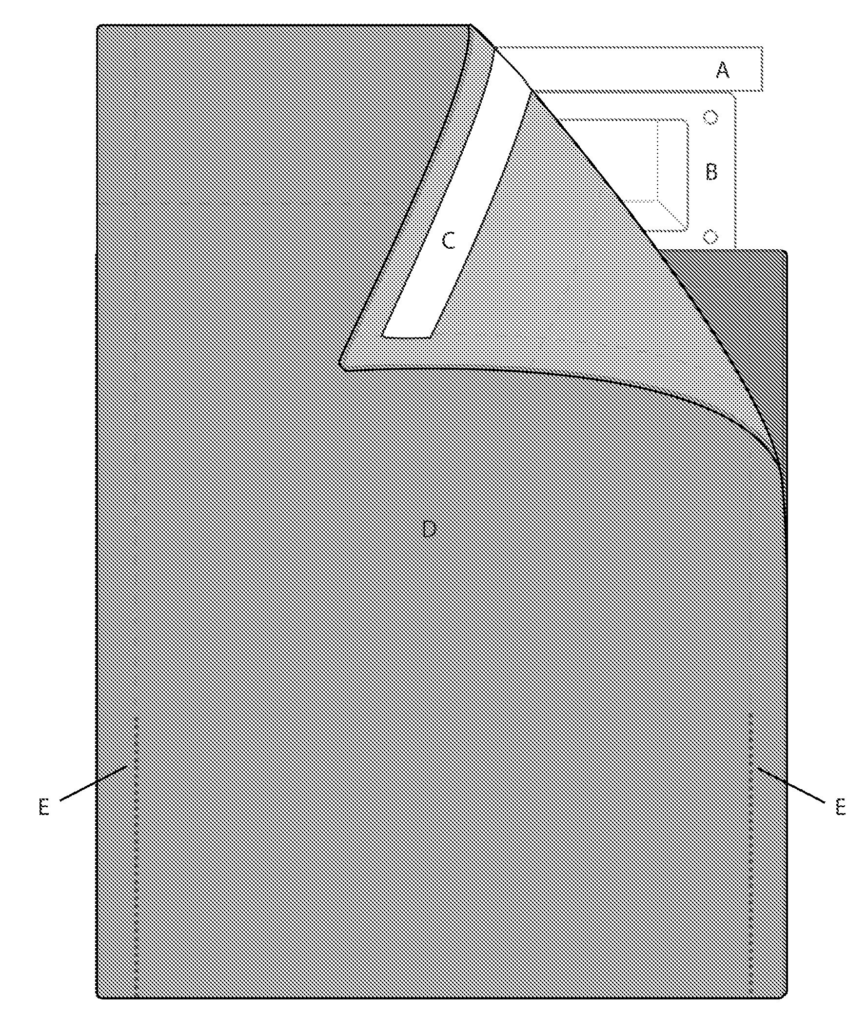
[0014]FIG. 1 is a front view of my new mail slot receptacle bag with the top right corner pulled downward to reveal how it would be mounted onto the interior side of a door or wall using Velcro (2) across the top of both panels of the bag (1) to hold it firmly in place above and below a mail slot. (C) designates the strips of velcro attached to the top, backside of both the longer and shorter panels of the bag. (C) adheres to (A) which are the strips of adhesive Velcro adhered to the door or wall with a mail slot. (B) refers to the mail slot itself; And, (D) refers to the whole mail bag invention. The longer and shorter panels of the bag are sealed or sewn together (E) along the sides towards the bottom portion of the bag, leaving the upper portion open for access into the bag from the sides.

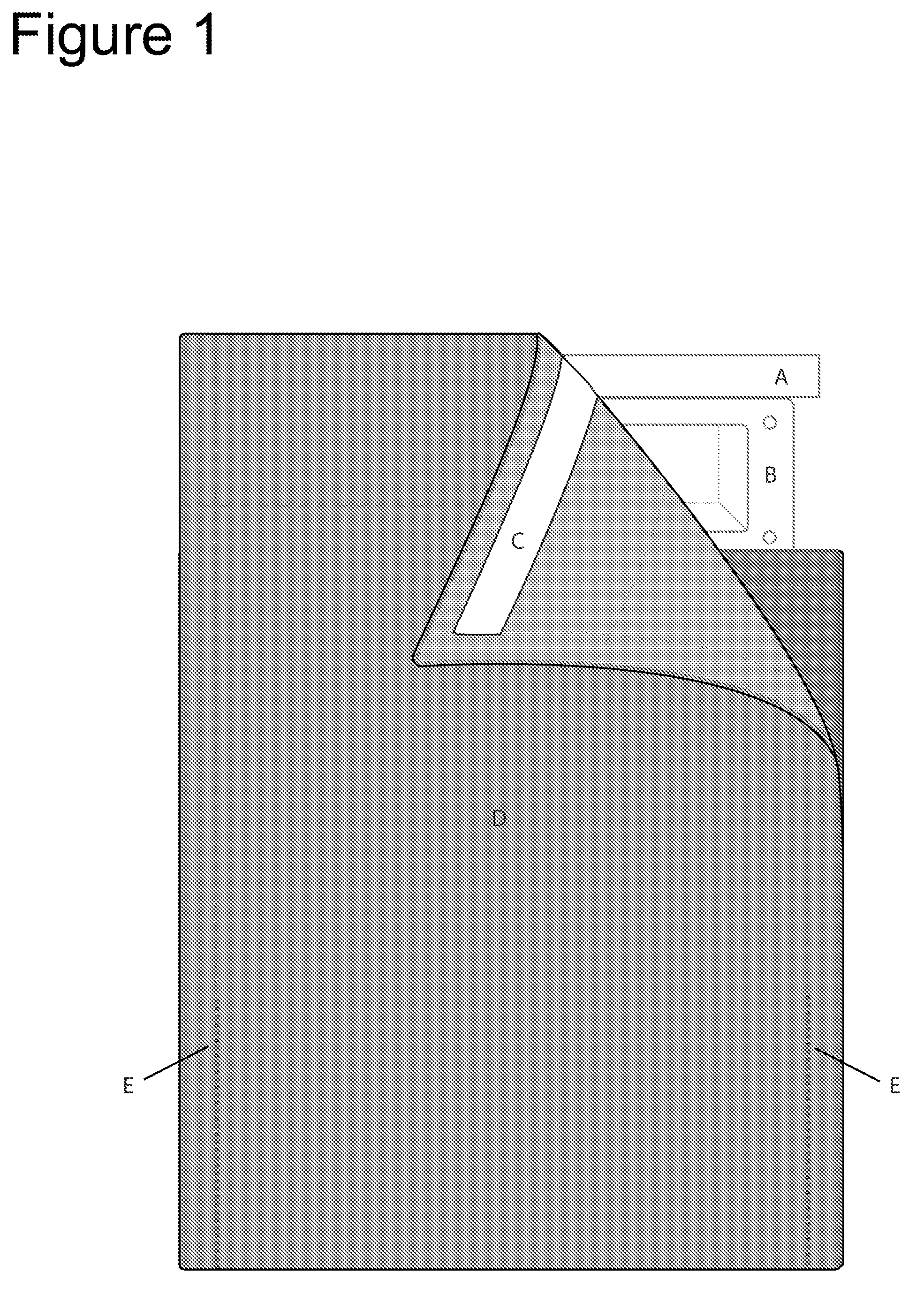
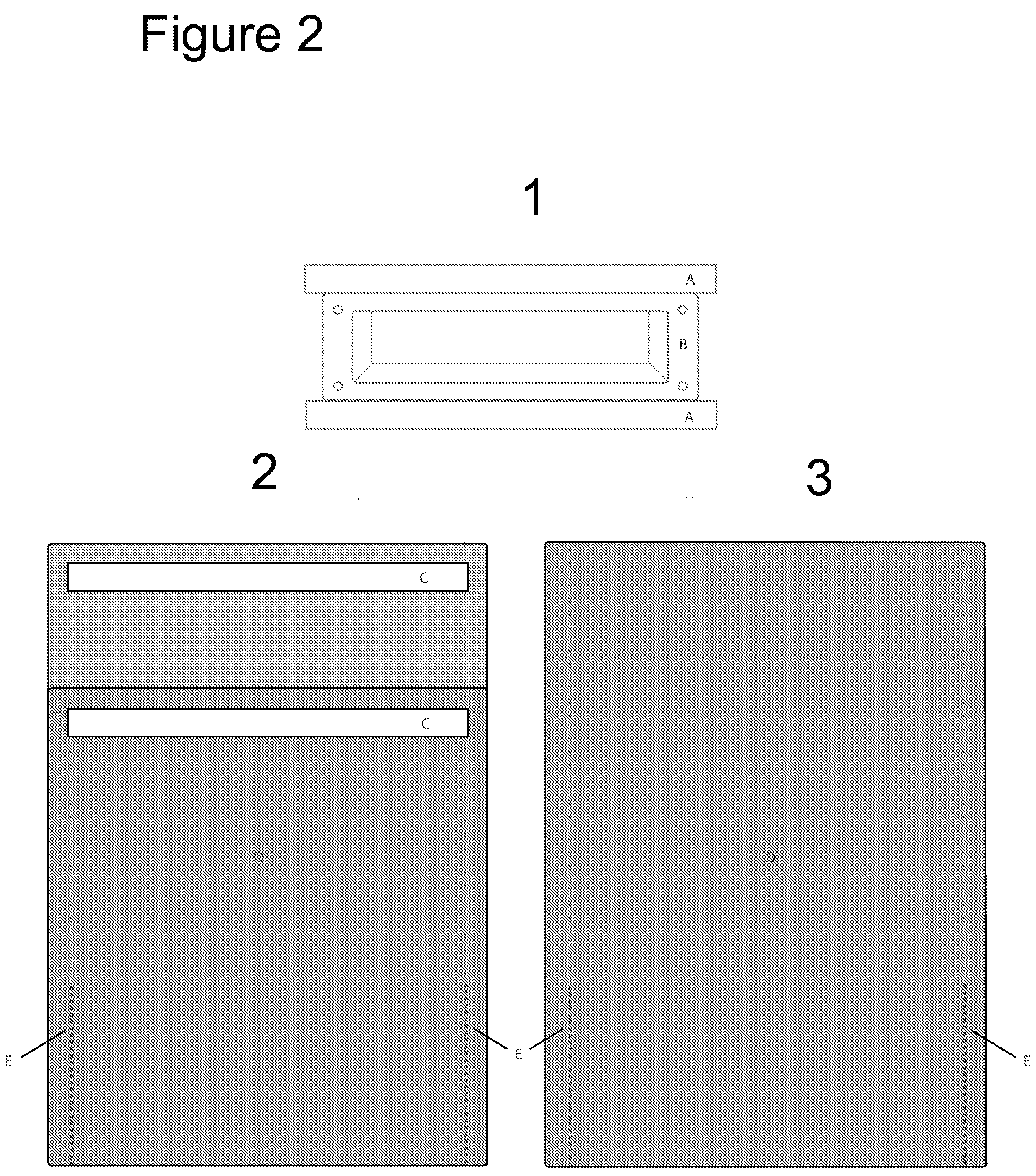
[0015]FIG. 2 first displays the interior side of a standard mail slot (B) with adhesive Velcro pieces (A) adhered above and below it (1). Next, the back view of my invention is displayed (2). He...


PUM


Abstract

A new and improved mail slot receptacle bag is provided for use with a door that has a mail slot therein. The top of the shorter panel of the bag adheres just below the mail slot, and the top of the longer panel of the bag adheres just above the mail slot. It is made of lightweight, yet sturdy fabric. There are slits on both sides of the sack to allow for easy accessibility to your mail. The slit openings also allow for more flexibility in the fabric when longer mail items are placed through the mail slot. The bag adheres to the door or wall using Velcro strips (which are concealed when bag is mounted). The Velcro strips allow for easy installation, easy removal of the bag whenever needed and avoids the damage that screws or nails would make to the door or wall. Below the side slits, the bottom ⅓rd of the bag's sides are sewn or closed so that mail will sit easily within.

Description

[0001]This application emanates from a previously filed application 61022763 Filed 22 Jan. 2008FIELD OF THE INVENTION[0002]The present invention relates generally to devices for receiving mail delivered to a residence or business, and, more particularly, to a pouch especially adapted for receiving mail deposited through a mail slot within a door or wall.BACKGROUND OF THE INVENTION[0003]Many devices have been used for receiving mail delivered to residential and commercial locations. Outdoor mailboxes have a number of disadvantages. They are exposed to extremes of weather, and they are often susceptible to unauthorized entry. Moreover, when an occupant of a dwelling goes on an extended vacation, the amount of mail that is received may cause an outdoor mailbox to overflow. For these reasons, mail slots in doors are especially desirable.[0004]Over the years, a handful of innovations have been developed relating to receptacles for receiving mail deposited through mail slots within a door...

Claims


Application Information

Patent Timeline
Patent Type & Authority Applications(United States)
IPC IPC(8): A47G29/12
CPCA47G29/12
Inventor CRAWFORD, CAMIE AMBER
Owner CRAWFORD CAMIE AMBER
Why Eureka
Try Eureka