Flat panel display mounting

Inactive Publication Date: 2009-07-23
TWIN STAR INT
View PDF7 Cites 66 Cited by
  • Summary
  • Abstract
  • Description
  • Claims
  • Application Information

AI Technical Summary

Benefits of technology

[0007]In accordance with one aspect of the present invention, a television mounting system includes a wall plate, at least one monitor arm mountable on the wall plate, and a rotating locking element permanently connected with the monitor arm. The rotating element may be moved between an unlocked position for enabling mounting and dismounting of the at least one monitor arm from the wall plate, and a locked position, for preventing dismounting of the at least one monitor arm from the wall plate, by rotating the rotating element a portion of a revolution. The rotating element includes a first side having a different height than a second side. When the rotating element is in the locked position and the at least one monitor arm is mounted on the wall plate, the first side of the rotating element is a first distance from a contact portion of the wall plate. The first distance is less than a second distance the monitor arm must be moved for dismounting the monitor arm from the wall plate, such that, with the rotating element in the locked position and the monitor arm mounted on the wall plate, the first side contacts the contact portion before the monitor arm can be moved the second distance, thereby preventing dismounting of the monitor arm from the wall plate.
[0008]In a further embodiment, when the rotating element is in the unlocked position and the at least one monitor arm is mounted on the wall plate, the second side of the rotating element is a third distance from the contact portion of the wall plate. The third distance is greater than the second distance, such that, with the rotating element in the unlocked position and the monitor arm mounted on the wall plate, the monitor arm can be moved a distance at least equal to the second distance before the second side contacts the contact portion of the wall plate, thereby enabling dismounting of the monitor from the wall plate.
[0010]In accordance with another aspect of the invention, the rotating locking element may be coupled with an extension element for extending the length of the rotating element.

Problems solved by technology

The locking mechanism typically is located within the narrow space between the mounted television and the wall, which makes user access to and operation of the mechanism difficult.
As the space between the mounted television and wall is typically very narrow, the engagement of the tool with the rotating element and rotating of the tool several revolutions may be difficult, especially when the distance between the rotating element and the edge of the mounted television is relatively large.

Method used


Image

  • Flat panel display mounting
  • Flat panel display mounting
  • Flat panel display mounting

Examples


Embodiment Construction

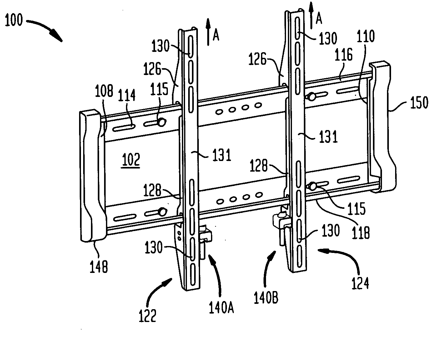
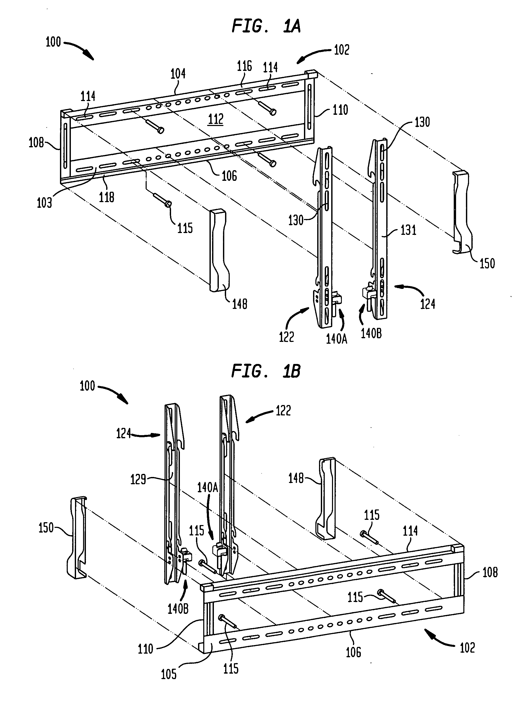
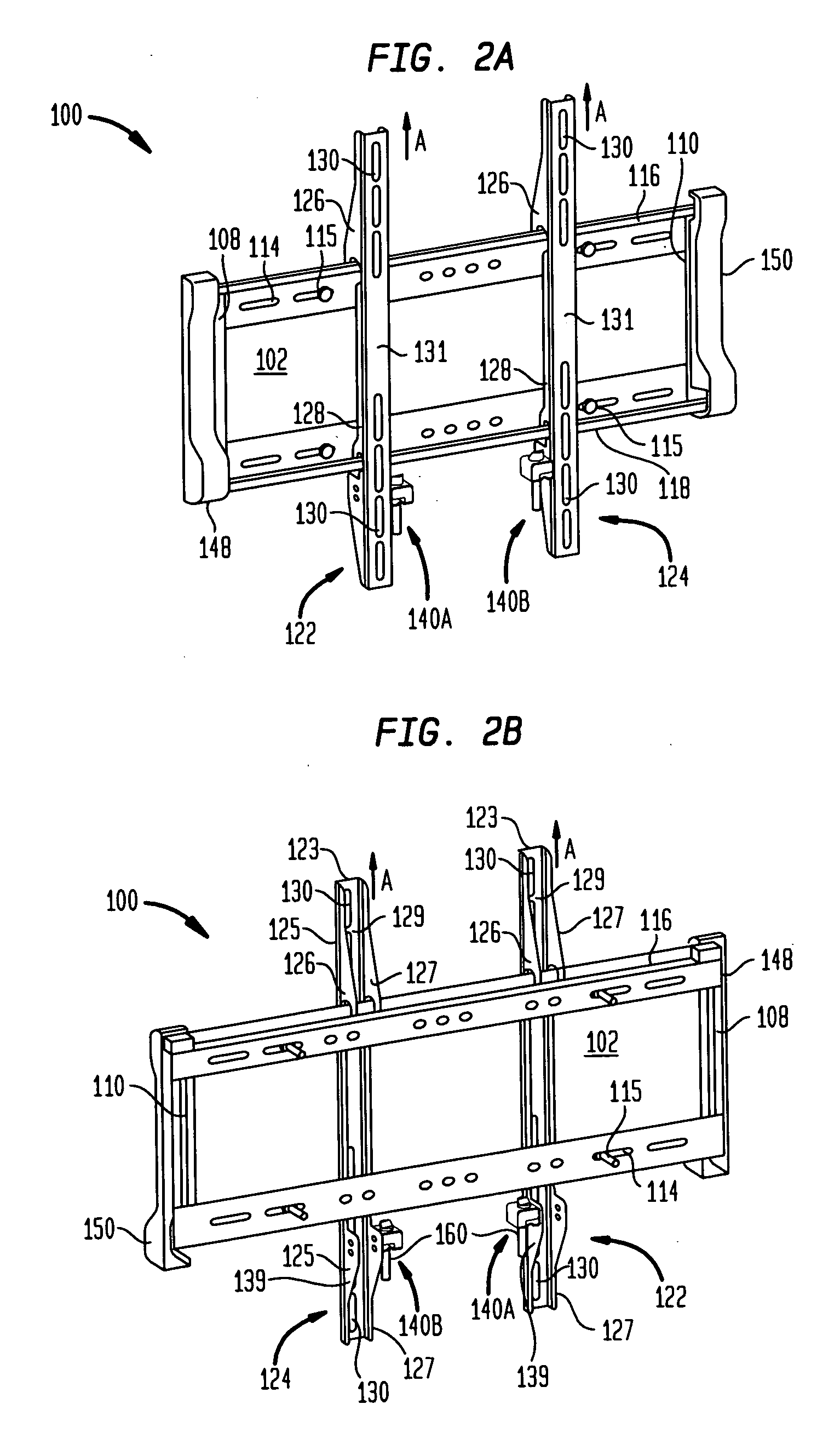
[0028]In accordance with an aspect of the present invention, referring to FIGS. 1A and 1B, an exemplary television mounting system 100 includes a wall plate 102 having an upper end 104, a lower end 106, a front side 103, a back side 105, a first end side 108 and a second end side 110. The wall plate 102 is desirably made of a sturdy material, such as metal. The wall plate 102 has a central opening 112 extending between the ends 104, 106 and the sides 108, 110. The opening 112 may be used for passing wires or cables through the wall plate 102, such as audio, video or power cables. The cables passed through the central opening 112 are desirably connected with a flat panel television or monitor for supplying power, audio or video to the television. The wall plate 102 also includes a plurality of mounting openings 114 disposed along the upper and lower ends 104, 106. The openings 114 may be used for securing the wall plate 102 to a wall or like surface using fastening screws 115. The te...


PUM


Abstract

A television mounting system includes a wall plate, at least one monitor arm mountable on the wall plate, and a locking mechanism including a rotating locking element permanently connected with the monitor arm. The rotating element is moveable, by rotation of the rotating element a portion of a revolution, between an unlocked position for enabling dismounting of the at least one monitor arm from the wall plate, and a locked position for preventing dismounting of the at least one monitor arm from the wall plate. The rotating element includes a first side having a different height than a second side. In the locked position of the locking element, the first side is less of a distance from a contact portion of the wall plate than a distance the monitor arm must be moved for dismounting the monitor arm from the wall plate, such that the locking element contacts the contact portion before the monitor can be moved for being dismounted from the wall plate.

Description

CROSS REFERENCE TO RELATED APPLICATION[0001]This application claims the benefit of the filing date of U.S. Provisional Patent Application No. 61 / 010,171 filed Jan. 4, 2008, the disclosure of which is hereby incorporated herein by reference.BACKGROUND OF THE INVENTION[0002]The present invention relates to television displays and more particularly relates to television mounting systems for flat panel displays.[0003]Recently, there has been a marked growth in the popularity of flat panel displays, and in particular flat panel televisions. Flat panel televisions presently use one of two technologies, either liquid crystal or plasma display, to provide a display screen that is much thinner and lighter than traditional cathode ray televisions or projection televisions. Flat panel televisions are also versatile in that they can be placed on a stand or mounted on numerous surfaces such as a wall.[0004]Typical systems for mounting a flat panel television to a wall include a wall mount, which...

Claims


Application Information

Patent Timeline
IPC IPC(8): A47B96/06
CPCF16M13/02
Inventor SCULLER, STEVEN J.
Owner TWIN STAR INT
Why Eureka
Try Eureka