Vehicle lane discrimination in an electronic toll collection system

Inactive Publication Date: 2009-07-23
MARK IV IVHS
View PDF9 Cites 28 Cited by
  • Summary
  • Abstract
  • Description
  • Claims
  • Application Information

AI Technical Summary

Benefits of technology

[0008]In one aspect, the present application describes a vehicle position determination system for determining a position of a moving vehicle having a transponder in a multi-lane roadway. The transponder is configured to transmit a probable lane response signal which is based on the number of instances the transponder has received a transmission from one or more communication sources. The determination system comprises two or more roadway antennas for receiving the probable lane response signal from the transponder. The roadway antennas have partially overlapped coverage zones and each roadway antenna has a unique identifier associated therewith. The determination system also includes a controller that is configured to cause each roadway antenna to periodically transmit its unique identifier.
[0009]In another aspect, the present application provides a transponder for a vehicle position determination system for tracking the position of a moving vehicle in a multi-lane roadway. The vehicle positioning system has at least two or more roadway antennas having partially overlapped coverage areas. Each roadway antenna has a unique identifier associated therewith and each roadway antenna periodically transmits its unique identifier. The transponder comprises a transponder antenna for receiving the unique identifier from at least one roadway antenna and transmitting a probable

Problems solved by technology

Lane identification is made difficul

Method used


Image

  • Vehicle lane discrimination in an electronic toll collection system
  • Vehicle lane discrimination in an electronic toll collection system
  • Vehicle lane discrimination in an electronic toll collection system

Examples


Embodiment Construction

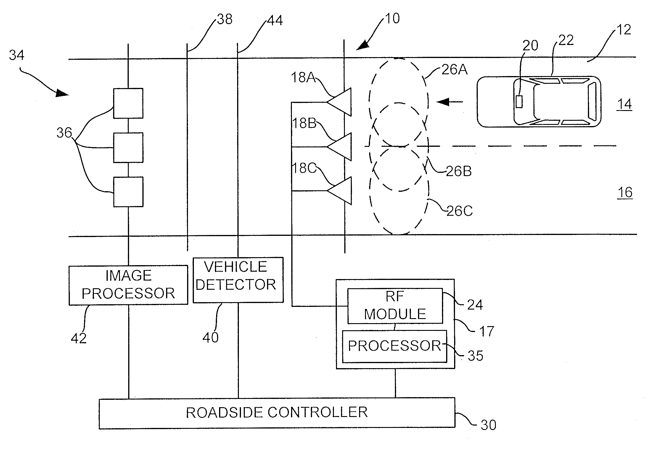
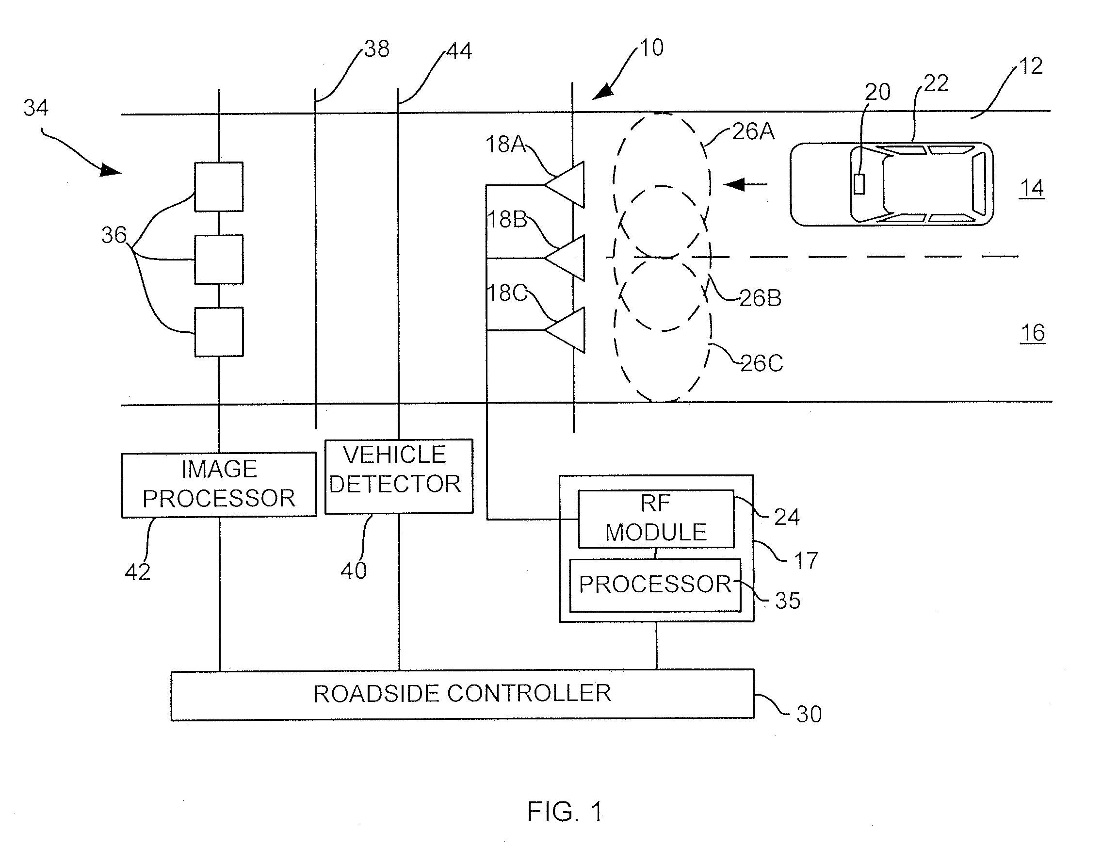
[0020]With reference to FIG. 1, there is shown an embodiment of a vehicle position determination system, illustrated generally by reference numeral 10. As shown in FIG. 1, the vehicle position determination system is applied to a roadway 12 having first and second adjacent lanes 14 and 16. The roadway 12 may be a two lane access roadway leading towards or away from a toll highway. The vehicle position determination system 10 includes three roadway antennas 18A, 18B and 18C, each of which is connected to signal processing means, namely an Automatic Vehicle Identification (“AVI”) reader 17. The AVI reader 17 processes signals that are sent and received by the roadway antennas 18A, 18B and 18C, and includes a processor 35 and a Radio Frequency (RF) module 24.

[0021]The RF module 24 is configured to modulate signals from the processor 35 for transmission as RF signals over the roadway antennas 18A, 18B and 18C, and to de-modulate RF signals received by the roadway antennas 18A, 18B and 1...


PUM


Abstract

A vehicle position determination system for determining the position of a moving vehicle in a multi-lane roadway. Two or more roadway antennas each periodically transmit an identifier that is associated with and unique to the antenna to a transponder located in the moving vehicle. As the moving vehicle passes through the coverage zone of the antennas, the transponder counts the number of times that it receives each unique identifier and reports this information to a roadside controller. Based on this information, the roadside controller can determine a probable location of the moving vehicle. The vehicle location information can be provided to an imaging system to discriminate between transponder and non-transponder equipped vehicles.

Description

FIELD OF THE INVENTION[0001]The present invention relates to electronic toll collection systems and, in particular, to methods and systems for determining a lane position of a moving vehicle having a transponder in a multi-lane roadway.BACKGROUND OF THE INVENTION[0002]Electronic toll collection systems are commonly used to facilitate the collection of a toll from a moving vehicle traveling on a toll-roadway.[0003]Automatic Vehicle Identification (“AVI”) is the process of determining the identity of a vehicle on the roadway. Typically, electronic toll systems use a series of antennas that are mounted near the roadway which provide coverage zones that extend the width of a lane. Radio frequency (“RF”) transponders are mounted on or within a vehicle to communicate with the antennas. A roadside AVI reader typically interrogates the transponder using the antenna. Typically, the roadside reader is connected to a vehicle detector and imaging system which permits vehicles to be detected, cl...

Claims


Application Information

Patent Timeline
IPC IPC(8): G08G1/123
CPCG08G1/017G07B15/063
Inventor KOHLI, JAPJEEVLAFFERTY, ROBERT
Owner MARK IV IVHS
Why Eureka
Try Eureka