Apparatus and method for thermal dissipation in a light

a technology of thermal dissipation and light, applied in the direction of lighting and heating apparatus, semiconductor devices for light sources, lighting support devices, etc., can solve the problems of restricting the effectiveness of heat removal capabilities of current techniques, suppressing the progress of producing new products with higher heat removal needs

Inactive Publication Date: 2009-07-23
NEXXUS LIGHTING
View PDF17 Cites 126 Cited by
  • Summary
  • Abstract
  • Description
  • Claims
  • Application Information

AI Technical Summary

Problems solved by technology

However, there tends to be a limit to the effectiveness of the heat removal capabilities of current techniques, which might suppress progress in producing new products that have higher heat removal needs.

Method used


Image

  • Apparatus and method for thermal dissipation in a light
  • Apparatus and method for thermal dissipation in a light
  • Apparatus and method for thermal dissipation in a light

Examples


Embodiment Construction

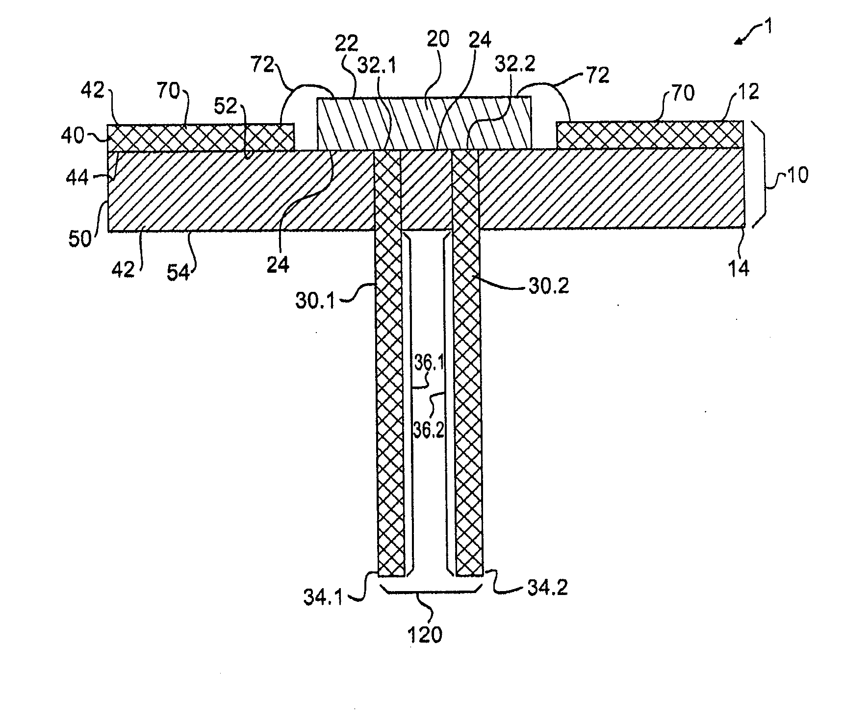
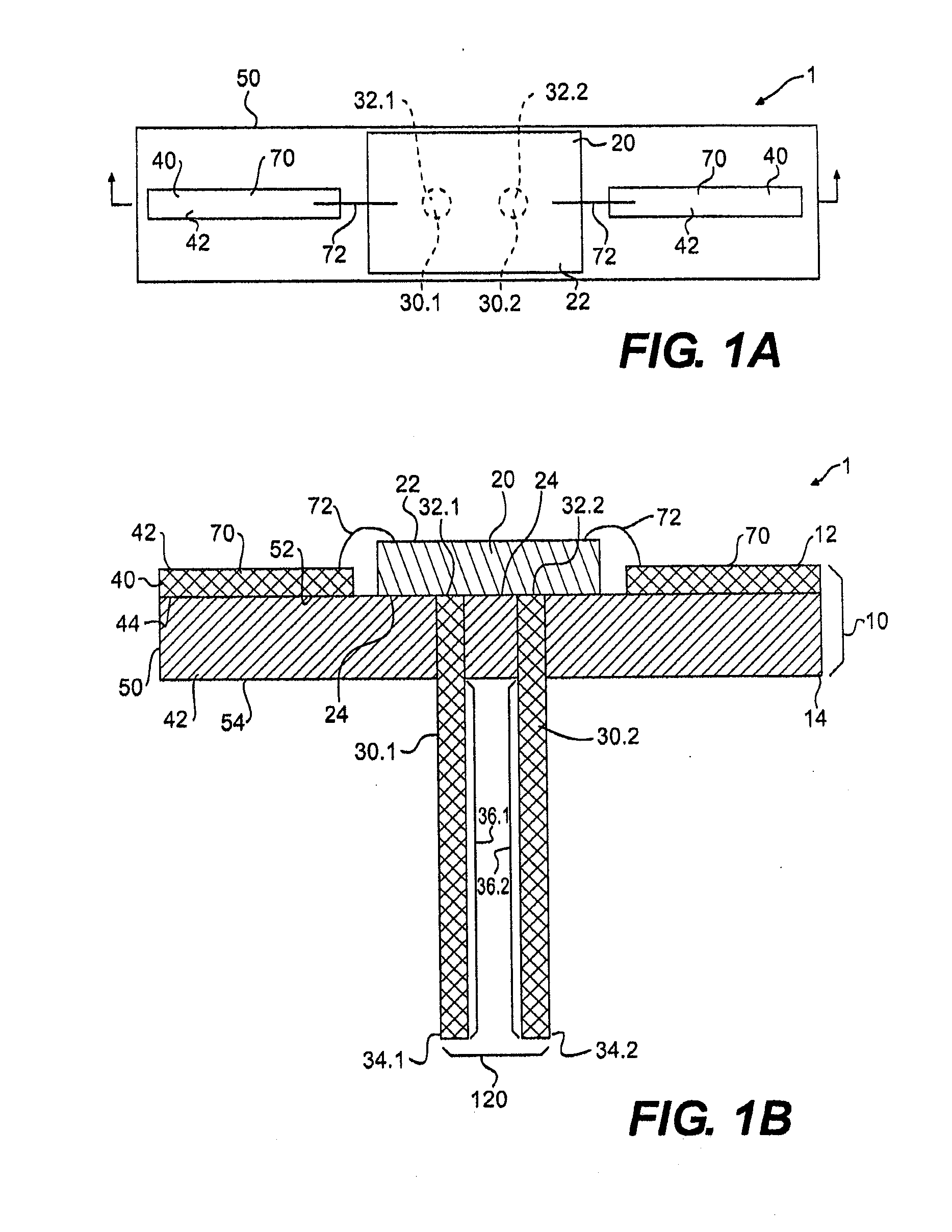
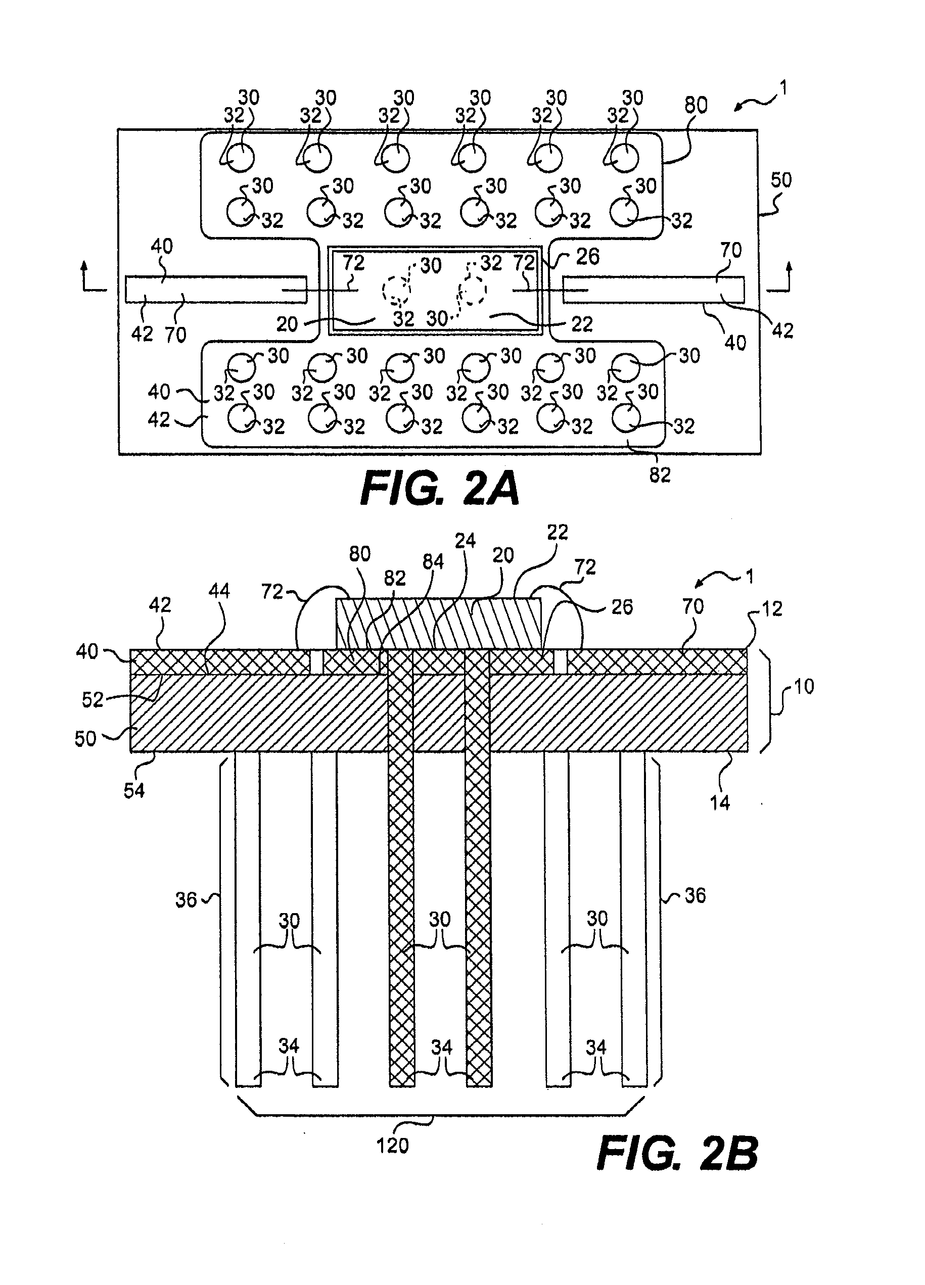
[0041]The embodiments of the invention and the various features and advantageous details thereof are explained more fully with reference to the non-limiting embodiments and examples that are described and / or illustrated in the accompanying drawings and detailed in the following description. It should be noted that the features illustrated in the drawings are not necessarily drawn to scale, and features of one embodiment may be employed with other embodiments as the skilled artisan would recognize, even if not explicitly stated herein. Descriptions of well-known components and processing techniques may be omitted so as to not unnecessarily obscure the embodiments of the invention. The examples used herein are intended merely to facilitate an understanding of ways in which the invention may be practiced and to further enable those of skill in the art to practice the embodiments of the invention. Accordingly, the examples and embodiments herein should not be construed as limiting the s...


PUM


Abstract

A device is disclosed for producing light that may include one or more printed circuit boards (PCBs), an electronics package may be disposed about the first surface of one or more of the PCBs and a housing. The PCBs may include a metal layer and a core, and, in some aspects, may include multiple cores interposed between multiple metal layers, and in some embodiments a backplane may be disposed along the core(s). A plurality of PCB's may be set apart and connected by pins to dissipate heat from one PCB to another, and / or to convey electrical connectivity. Pins may be configured to pass through or into one or both the PCBs including the cores to conduct heat generated by the electronics package away for dispersion. In some embodiments, the pins may pass into the backplane. The PCBs may include LEDs, lights, computer devices, memories, telecommunications devices, or combinations of these. The device may also include a housing to contain the plurality of PCBs such that air flow may enter the housing and pass by the pins for cooling of the PCBs and electronics thereof. The housing may also be configured to permit external power to be applied to the PCBs within the apparatus.

Description

CROSS-REFERENCE TO RELATED APPLICATIONS[0001]This application claims priority under 35 U.S.C. §119(e) to provisional U.S. Patent Application No. 60 / 988,954, filed on Nov. 19, 2007 and to provisional U.S. Patent Application No. 61 / 096,273, filed on Sep. 11, 2008, the disclosures of which are expressly incorporated by reference herein in their entirety.BACKGROUND OF THE INVENTION[0002]1. Field of the Invention[0003]The invention is directed generally to a method and device for the thermal management of heat in electronic devices. More particularly, the invention is directed to thermal management of heat in electronic devices having printed circuit boards that may include light emitting diodes, or the like.[0004]2. Related Art[0005]Numerous electronic manufacturing techniques have attempted to deal with component placement on printed circuit boards (PCB) to minimize costs for producing electronic products. For many products, the types of electronic components involved may dictate parti...

Claims


Application Information

Patent Timeline
Patent Type & Authority Applications(United States)
IPC IPC(8): F21V21/00F21V29/00
CPCH01L2224/48091F21V29/2275H01L2224/48227F21V29/83F21Y2101/02F28F3/022H01L33/642H05K1/0204F21V21/00F21V29/2206H05K2201/066H05K2201/10106F21V23/06F21K9/137F21V29/004F21V29/74F21V29/773F21V29/80H01L2924/00014F21K9/233F21Y2115/10
Inventor GRAJCAR, ZDENKO
Owner NEXXUS LIGHTING
Why Eureka
Try Eureka