Air ventilation system

a technology of air ventilation and air flow rate, which is applied in ventilation systems, lighting and heating apparatus, heating types, etc., can solve the problems of high cost of maintaining a high flow rate, explosion and release of toxic gasses into the surrounding environment, and reduce the cost of operating semiconductor manufacturing equipment, so as to reduce the amount of conditioned air.

Inactive Publication Date: 2009-07-23
ASM IP HLDG BV
View PDF3 Cites 326 Cited by
  • Summary
  • Abstract
  • Description
  • Claims
  • Application Information

AI Technical Summary

Benefits of technology

[0007]As set forth in the detailed description and accompanying figures, the present invention comprises, in various exemplary embodiments, a device configured to overcome a typical ventilation system's shortcomings by providing a system and device that adjusts the air flow within an enclosure used for semiconductor manufacturing based upon the occurrence of one or more conditions. As a result, the ventilation system of the present invention reduces the cost to operate semiconductor manufacturing equipment because of the reduced amount of conditioned air that is consumed.

Problems solved by technology

Semiconductor manufacturing requires numerous gasses that are highly explosive, toxic, corrosive, or otherwise harmful.
Allowing these gasses to build up within the enclosures can lead to explosions and releases of the toxic gasses into the surrounding environment.
Maintaining a high flow rate can be expensive as the air used must generally be conditioned for temperature, humidity, particles, and other factors that are typically required in the manufacture of semiconductors.
Such conditioning is costly and can exceed tens of thousands of dollars per machine on an annual basis.
Because current semiconductor manufacturing tools utilize a high flow rate the entire time they operate regardless of whether such a high flow rate is actually needed, these tools consume a tremendous amount of energy and money.

Method used


Image

  • Air ventilation system
  • Air ventilation system
  • Air ventilation system

Examples


Embodiment Construction

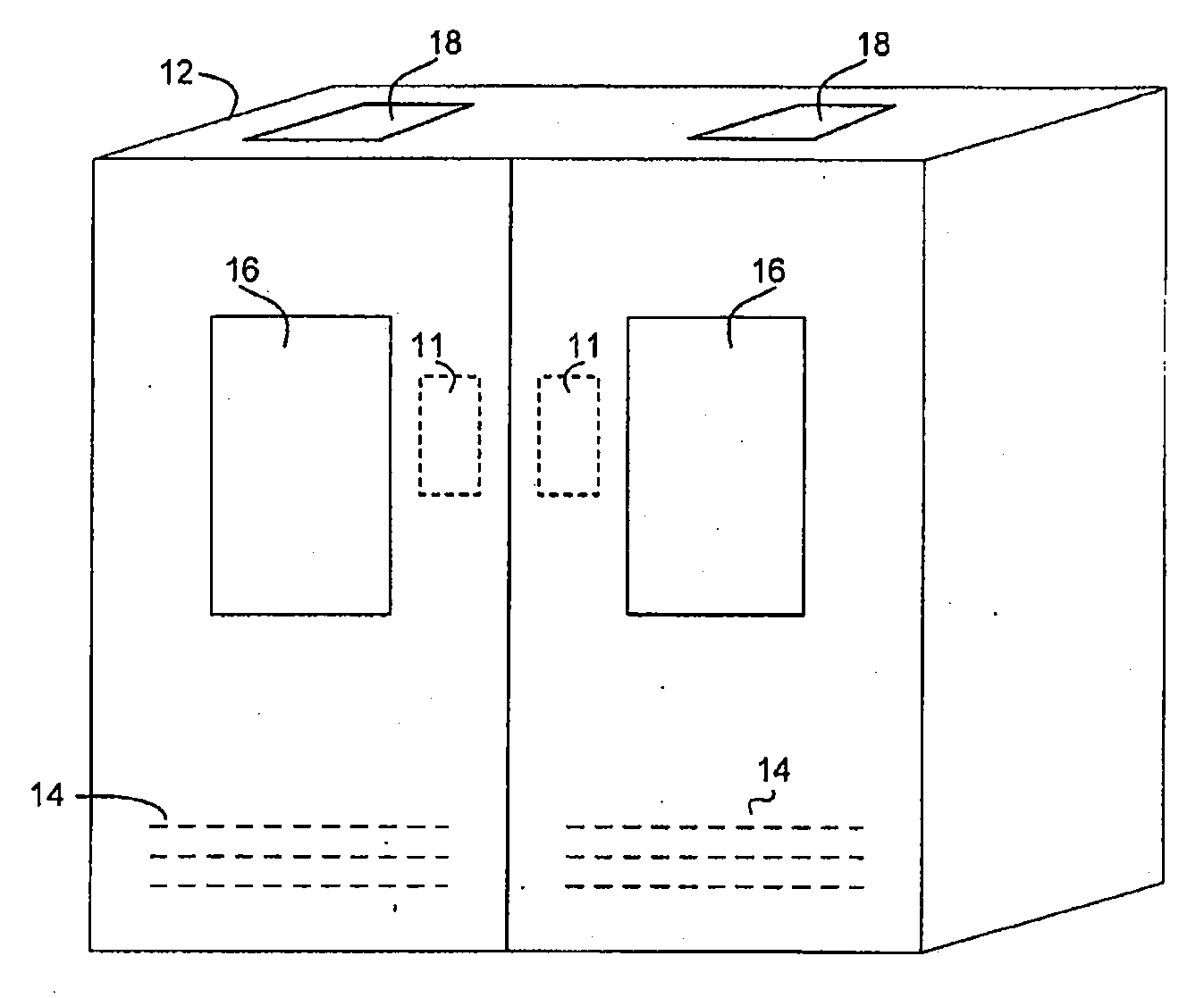
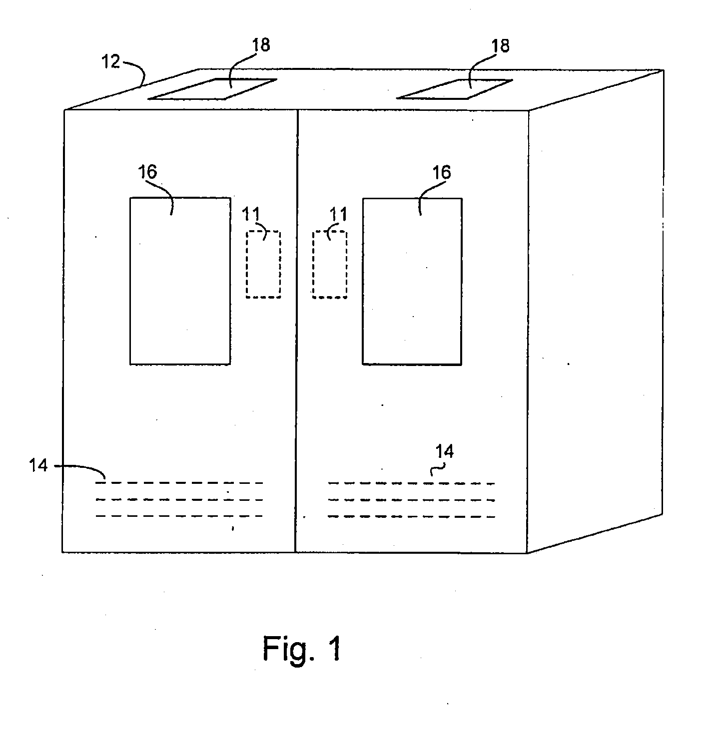
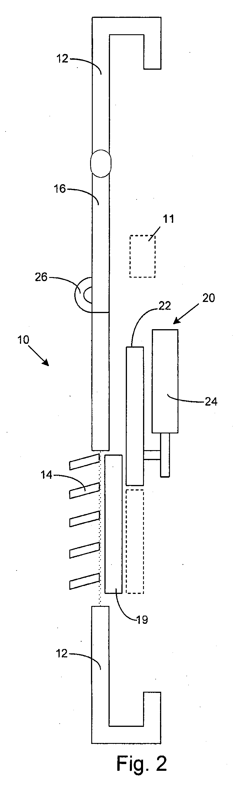
[0016]The detailed description of various exemplary embodiments of the invention herein makes reference to the accompanying figures. While these exemplary embodiments are described in sufficient detail to enable those skilled in the art to practice the invention, it should be understood that other embodiments may be realized and that logical and mechanical changes may be made without departing from the spirit and scope of the invention. Thus, the detailed description herein is presented for purposes of illustration only and not of limitation. Additionally, while the disclosure herein describes the present invention used in connection with semiconductor manufacturing and processing, it should be noted that the air ventilation restriction system can be used with any ventilation system or area receiving circulating air.

[0017]In accordance with various exemplary embodiments of the present invention, an air ventilation restriction system for use with semiconductor manufacturing or proces...


PUM


Abstract

The present invention is directed at an air ventilation system for use with semiconductor manufacturing equipment. Specifically, the ventilation system of the present invention adjusts vents or outlets located on an enclosure used for semiconductor manufacturing between a restricted state and an open state. When the vents and / or outlets are in an open state, a high flow rate through the enclosure is able to properly scavenge toxic and volatile gasses to safely remove them. When the vents and / or outlets are in a restricted state, the flow rate of gases therethrough is substantially or fully restricted. Upon the sensing of a condition (or the lack thereof) or the manual operation of an operator, the vents and / or outlets are selectively adjusted between the restricted and open states.

Description

FIELD OF INVENTION[0001]The invention relates to an automated air ventilation system for use with enclosures such as those used in semiconductor manufacturing and processing. More particularly, the device of the present invention comprises an automated ventilation system that enables an enclosure to only have the maximum flow rate when desired, for example, based on the presence or absence of one or more conditions that require a high flow rate.BACKGROUND OF THE INVENTION[0002]Semiconductor manufacturing requires numerous gasses that are highly explosive, toxic, corrosive, or otherwise harmful. These gasses are typically found in numerous machines and processing tools that include enclosures that are used (in part) to prevent the gasses from escaping into the immediate working environment and causing harm. Allowing these gasses to build up within the enclosures can lead to explosions and releases of the toxic gasses into the surrounding environment.[0003]To prevent gas buildup withi...

Claims


Application Information

Patent Timeline
Patent Type & Authority Applications(United States)
IPC IPC(8): F24F7/00
CPCH01L21/67017
Inventor HARO, ROBERT C.
Owner ASM IP HLDG BV
Why Eureka
Try Eureka