Capacitor-integrated feedthrough assembly with improved grounding for an implantable medical device

a feedthrough assembly and capacitor technology, applied in the direction of feed-through capacitors, fixed capacitors, therapy, etc., can solve the problems of high cost, high cost, and high cost of capacitors, and achieve the effect of occupying premium space in prior art feedthrough assemblies

Active Publication Date: 2009-07-23
PACESETTER INC
View PDF22 Cites 140 Cited by
  • Summary
  • Abstract
  • Description
  • Claims
  • Application Information

AI Technical Summary

Benefits of technology

[0007]What is described herein is a shielded feedthrough assembly for coupling implantable patient leads to electrical and other operational circuitry of an implantable medical device. In one implementation, the feedthrough assembly includes one or more feedthrough wires, an insulator, and a feedthrough case. In one embodiment, the feedthrough case is connected to a mechanical support comprised, in one specific embodiment, of multiple ceramic layers. One or more filtering capacitors are disposed inside a wire bonding ceramic substrate of the mechanical support to filter and inhibit transmission of undesired frequencies from electrical signals received through the implanted patient leads. The shielded feedthrough assembly, feedthrough wires, the mechanical support, and a housing of the implantable medical device act in combination to provide a shield between the environment and the sensitive circuitry of the device.

Problems solved by technology

The capacitors are very specialized, difficult to manufacture, and are therefore expensive.
Because of the specialized type capacitors, prior art feedthrough assemblies occupy premium space.
An increase in the size of the implantable device may result in added discomfort to the patient while a decrease in size can reduce potential irritation for the patient.
Further, due to the limited possible size of these devices, the amount of space inside the device is also limited.
Smaller components may create space for additional features, while a larger component may limit the size for other features and components.

Method used


Image

  • Capacitor-integrated feedthrough assembly with improved grounding for an implantable medical device
  • Capacitor-integrated feedthrough assembly with improved grounding for an implantable medical device
  • Capacitor-integrated feedthrough assembly with improved grounding for an implantable medical device

Examples


Embodiment Construction

[0022]Reference will now be made to the drawings wherein like numerals refer to like parts throughout. The following description is of the best mode presently contemplated for practicing the invention. This description is not to be taken in a limiting sense but is made merely for the purpose of describing the general principles of the invention. The scope of the invention should be ascertained with reference to the issued claims. In the description of the invention that follows, like numerals or reference designators will be used to refer to like parts or elements throughout.

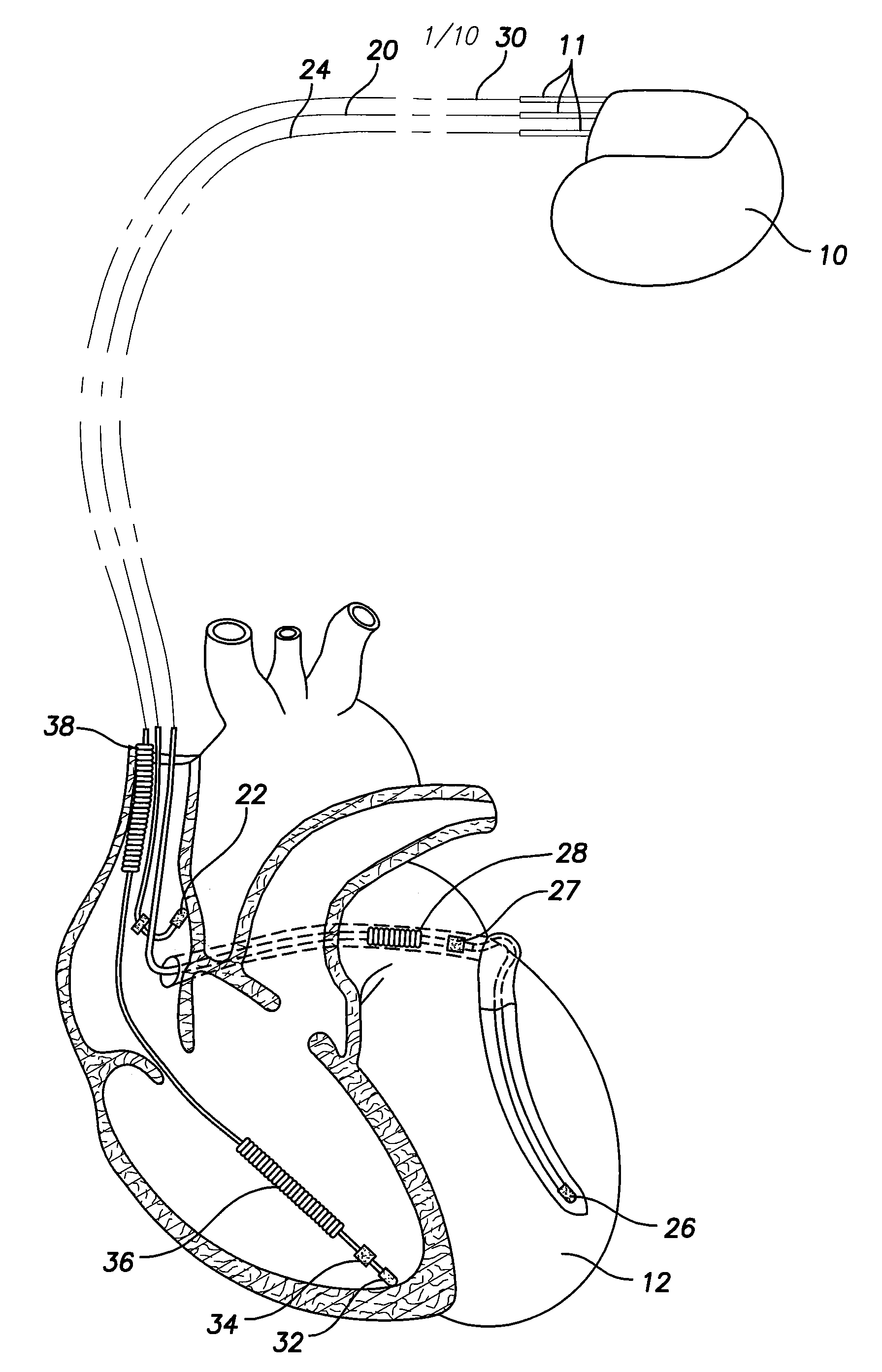
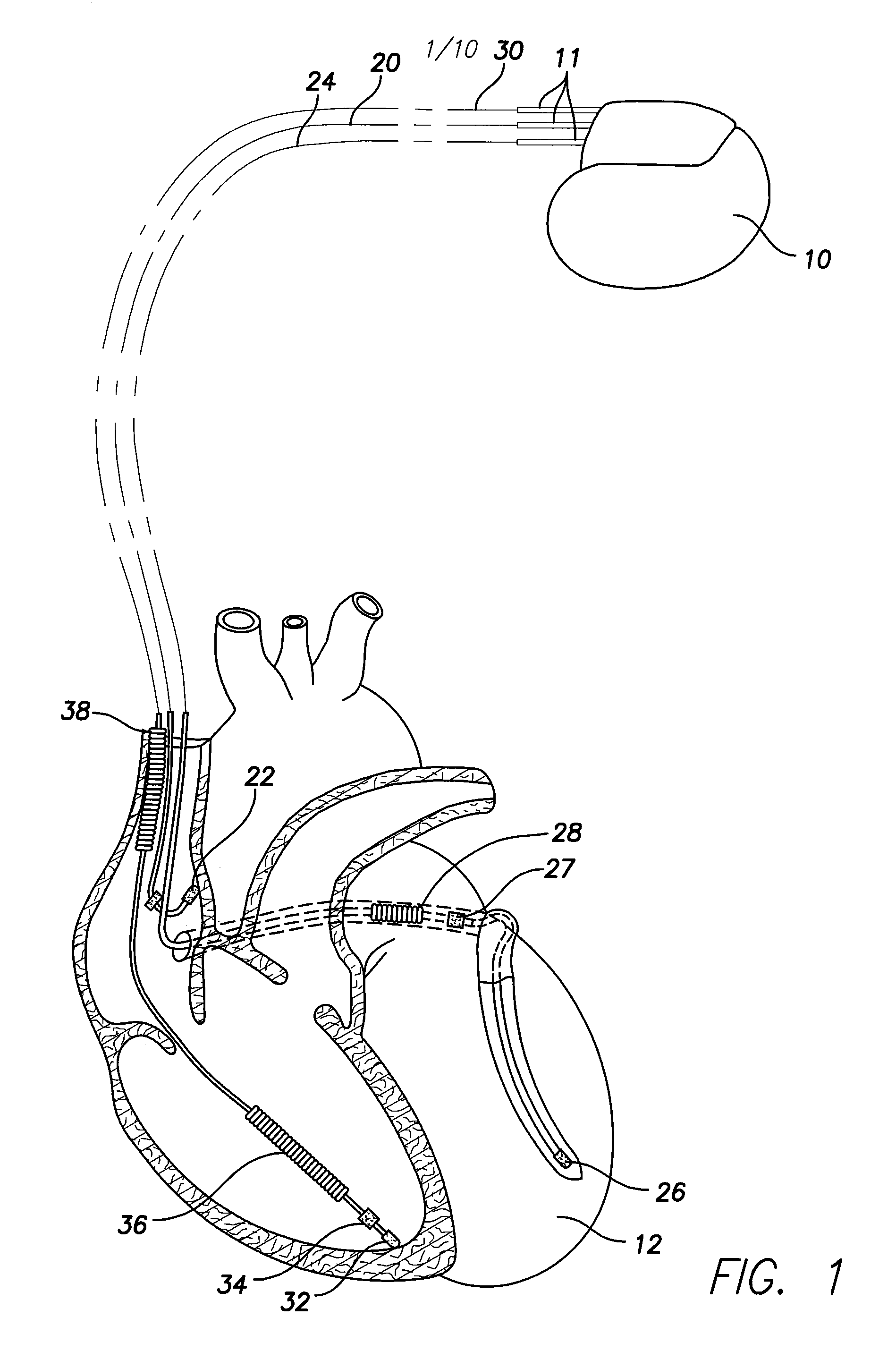
[0023]In one embodiment, as shown in FIG. 1, a device 10 comprising an implantable cardiac stimulation device 10, is in electrical communication with a patient's heart 12 by way of three leads, 20, 24 and 30, suitable for delivering multi-chamber stimulation and shock therapy. To sense atrial cardiac signals and to provide right atrial chamber stimulation therapy, the stimulation device 10 is coupled to an impla...


PUM


Abstract

A feedthrough assembly for use with implantable medical devices having a shield structure, the feedthrough assembly engaging with the remainder of the associated implantable medical device to form a seal with the medical device to inhibit unwanted gas, liquid, or solid exchange into or from the device. One or more feedthrough wires extend through the feedthrough assembly to facilitate transceiving of the electrical signals with one or more implantable patient leads. The feedthrough assembly is connected to a mechanical support which houses one or more filtering capacitors that are configured to filter and remove undesired frequencies from the electrical signals received via the feedthrough wires before the signals reach the electrical circuitry inside the implantable medical device.

Description

CROSS REFERENCE TO RELATED APPLICATIONS[0001]This application is a continuation-in-part of U.S. patent application Ser. No. 11 / 734,145, filed Apr. 11, 2007 entitled “CAPACITOR-INTEGRATED FEEDTHROUGH ASSEMBLY FOR AN IMPLANTABLE MEDICAL DEVICE,” which is hereby incorporated by reference in its entirety.FIELD OF THE INVENTION[0002]The invention relates generally to implantable medical devices and more particularly to shielded feedthrough structures that connect one or more implantable patient leads to various operational circuitry within the housing of the implantable medical devices while maintaining a hermetic seal of the devices.BACKGROUND OF THE INVENTION[0003]A variety of implantable medical devices have been developed and employed for long-term implanted monitoring of one or more patient physiological conditions and / or delivery of indicated therapy. Implantable cardiac stimulation devices are one particular category of implantable devices which are adapted to monitor the patients...

Claims


Application Information

Patent Timeline
Patent Type & Authority Applications(United States)
IPC IPC(8): A61N1/375
CPCA61N1/3752H01M6/04A61N1/3754Y10S439/909
Inventor LAVIE, ZEEV
Owner PACESETTER INC
Why Eureka
Try Eureka