
Phase Shifter And Antenna Including Phase Shifter

Active Publication Date: 2009-07-30
COMMSCOPE INC
View PDF12 Cites 18 Cited by
  • Summary
  • Abstract
  • Description
  • Claims
  • Application Information

AI Technical Summary

Benefits of technology

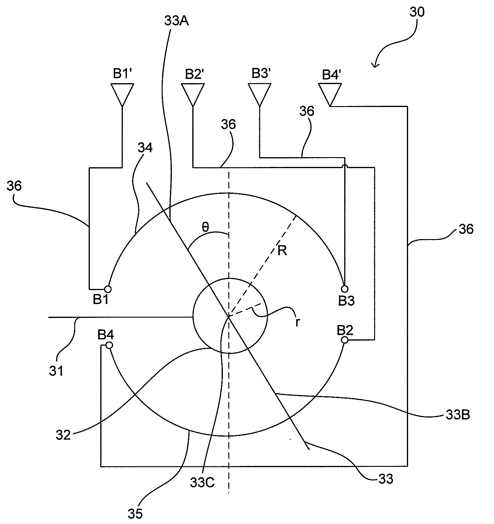
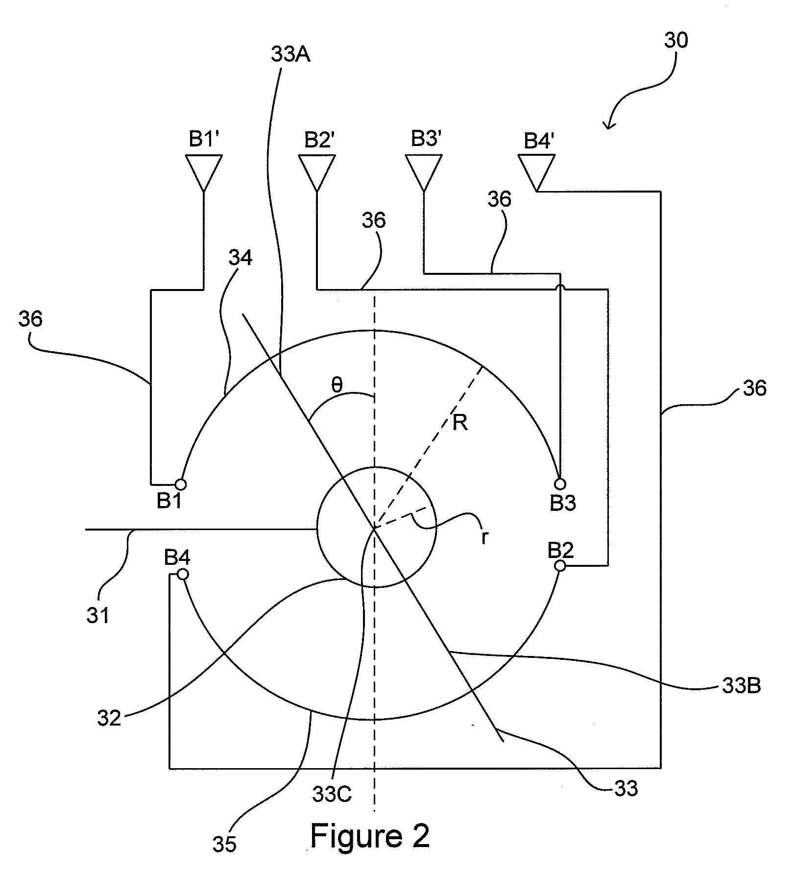
[0018]There is provided a wiper-type phase shifter and an antenna including a wiper-type phase shifter. The antenna elements and the phase shifter are arranged in such a manner that phase errors present in prior devices are reduced. In particular, a first antenna element intended to have a greatest positive phase shift and a second antenna element intended to have a greatest negative phase shift are connected to different arcs in the phase shifter.
[0019]There is also provided a wiper-style phase shifter which is more compact than prior phase shifters and / or provides a greater phase shift than prior phase shifters of equivalent dimensions. The arcs in the phase shifter may be arranged for increased electrical length. The wiper may be arranged for increased electrical length.

Problems solved by technology

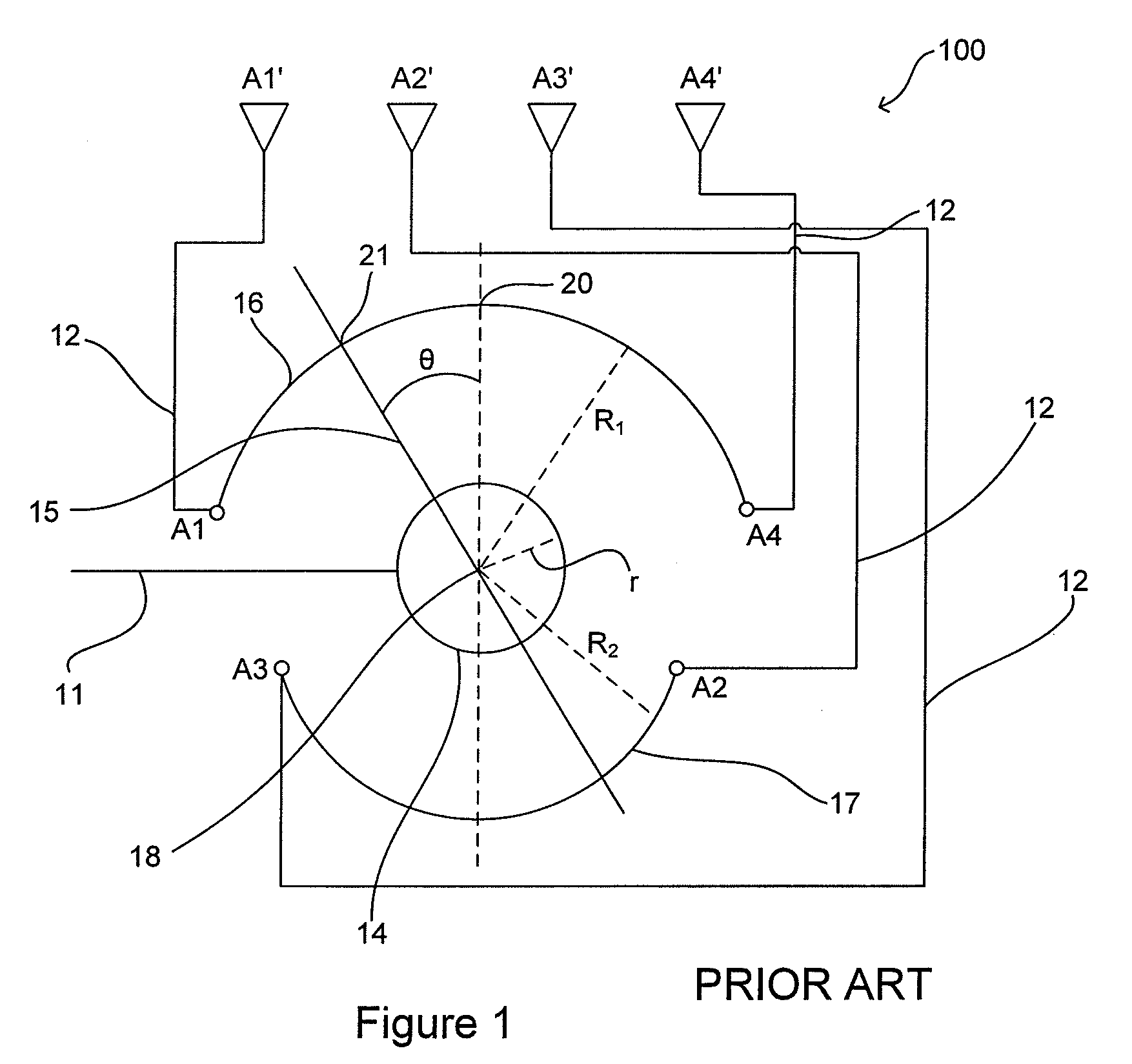
The Applicant has found that the configuration shown in FIG. 1 introduces undesirable phase errors.
Furthermore, the phase shifts introduced between all pairs of adjacent antenna elements cannot be made equal.
These are undesirable phase errors which have a negative impact on the performance of an antenna including the phase shifter.
Wiper phase shifters are also generally bulky and therefore unsuitable for some applications.

Method used


Image

  • Phase Shifter And Antenna Including Phase Shifter
  • Phase Shifter And Antenna Including Phase Shifter
  • Phase Shifter And Antenna Including Phase Shifter

Examples


Embodiment Construction

[0018]There is provided a wiper-type phase shifter and an antenna including a wiper-type phase shifter. The antenna elements and the phase shifter are arranged in such a manner that phase errors present in prior devices are reduced. In particular, a first antenna element intended to have a greatest positive phase shift and a second antenna element intended to have a greatest negative phase shift are connected to different arcs in the phase shifter.

[0019]There is also provided a wiper-style phase shifter which is more compact than prior phase shifters and / or provides a greater phase shift than prior phase shifters of equivalent dimensions. The arcs in the phase shifter may be arranged for increased electrical length. The wiper may be arranged for increased electrical length.

[0020]In one exemplary embodiment there is provided an antenna including a plurality of antenna elements and a feed network configured to feed signals to and / or receive signals from the antenna elements, wherein t...


PUM


Abstract

A phase shifter includes two or more conductive strips, an input line and a wiper coupled to both the input line and the conductive strips. Rotation of the wiper about a pivot point alters the path lengths between the input line and output ports or antenna elements connected to the conductive strips. The wiper is a multi-bladed wiper. Phase errors in multi-bladed wiper-type phase shifters are reduced. Arrangements for reduction of phase shifter size or increase in phase shift range are described.

Description

FIELD OF THE INVENTION[0001]The invention relates to phase shifters, particularly but not exclusively to multi-bladed wiper-type phase shifters for use in cellular communications antennas.BACKGROUND TO THE INVENTION[0002]Cellular antennas often include phase shifters for adjusting the phase of signals supplied to or received from radiating elements. Adjustment of phase may be used for electronic steering of beam angle, such as electronic downtilt.[0003]Differential phase shifters adjust the phase between a pair of signal ports. A positive phase shift is applied to one of the ports and a negative phase shift is applied to the other port.[0004]One known type of phase shifter is the “wiper” phase shifter 100 shown schematically in FIG. 1. Signals are received by the phase shifter over an input line 11 and transmitted through the phase shifter to a number of signal ports A1, A2, A3 and A4. Signals are supplied from the ports A1, A2, A3 and A4 to radiating elements A1′, A2′, A3′ and A4′ ...

Claims


Application Information

Patent Timeline
IPC IPC(8): H01Q21/00
CPCH01Q3/32H01P1/184H01Q1/241H01Q1/38H01Q9/0407
Inventor TIMOFEEV, IGOR E.ZIMMERMAN, MARTIN L.XIANGYANG, AI
Owner COMMSCOPE INC
Learn More