Image forming apparatus

a technology of image forming apparatus and recording head, which is applied in the direction of printing, other printing apparatus, etc., can solve the problems of reducing image quality, unable to determine whether, and measurement from the vertically downward position using the laser beam sensor may not provide accurate measurement, so as to prevent a reduction in image quality and accurately detect the inclination of the recording head

Inactive Publication Date: 2009-07-30
RICOH KK
View PDF22 Cites 12 Cited by
  • Summary
  • Abstract
  • Description
  • Claims
  • Application Information

AI Technical Summary

Benefits of technology

[0019]The above-described image forming apparatus forms a print pattern on the transport belt by ejecting droplets from at least nozzles at the opposing ends of the nozzle array of the line type recording head, measures the print positions of the plural points of the print pattern, which are located at different positions in the nozzle arrangement direction, in the direction orthogonal to the nozzle arr

Problems solved by technology

However, even if the recording head is positioned with high accuracy at the time of manufacture, the head position may be changed with time or may be changed when replacing the recording head due to malfunction or the like.
If the installed state (mounted state) of the recording head is changed as described above, a droplet impact position shift may occur, resulting in reduced image quality.
However, the devices disclosed in Patent Documents 1-4 cannot detect a change in the recording head attachment position and hence cannot determine whether the impact position shift is caused due to a change in the recording head attachment position.
Moreover, measurement from the vertically downward po

Method used


Image

  • Image forming apparatus
  • Image forming apparatus
  • Image forming apparatus

Examples


Embodiment Construction

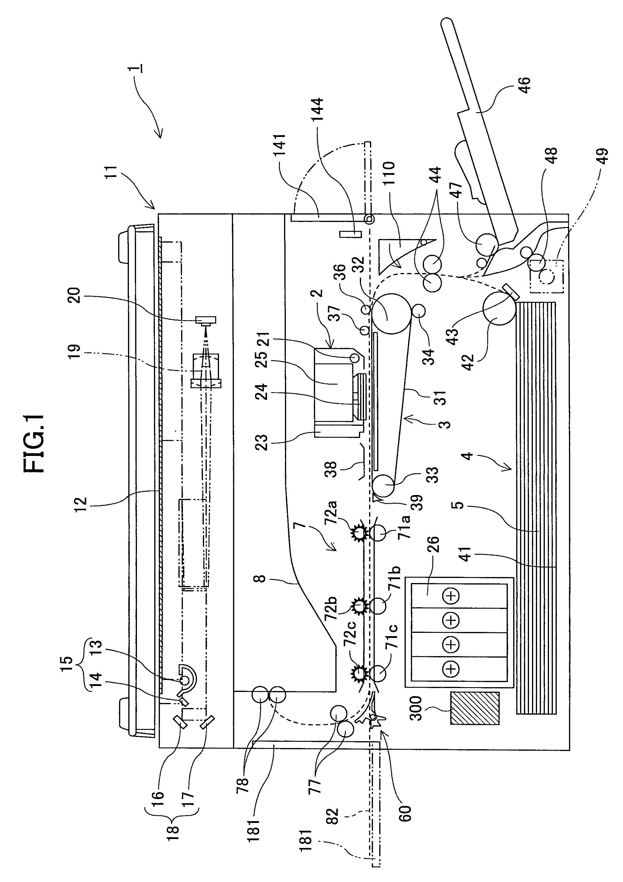
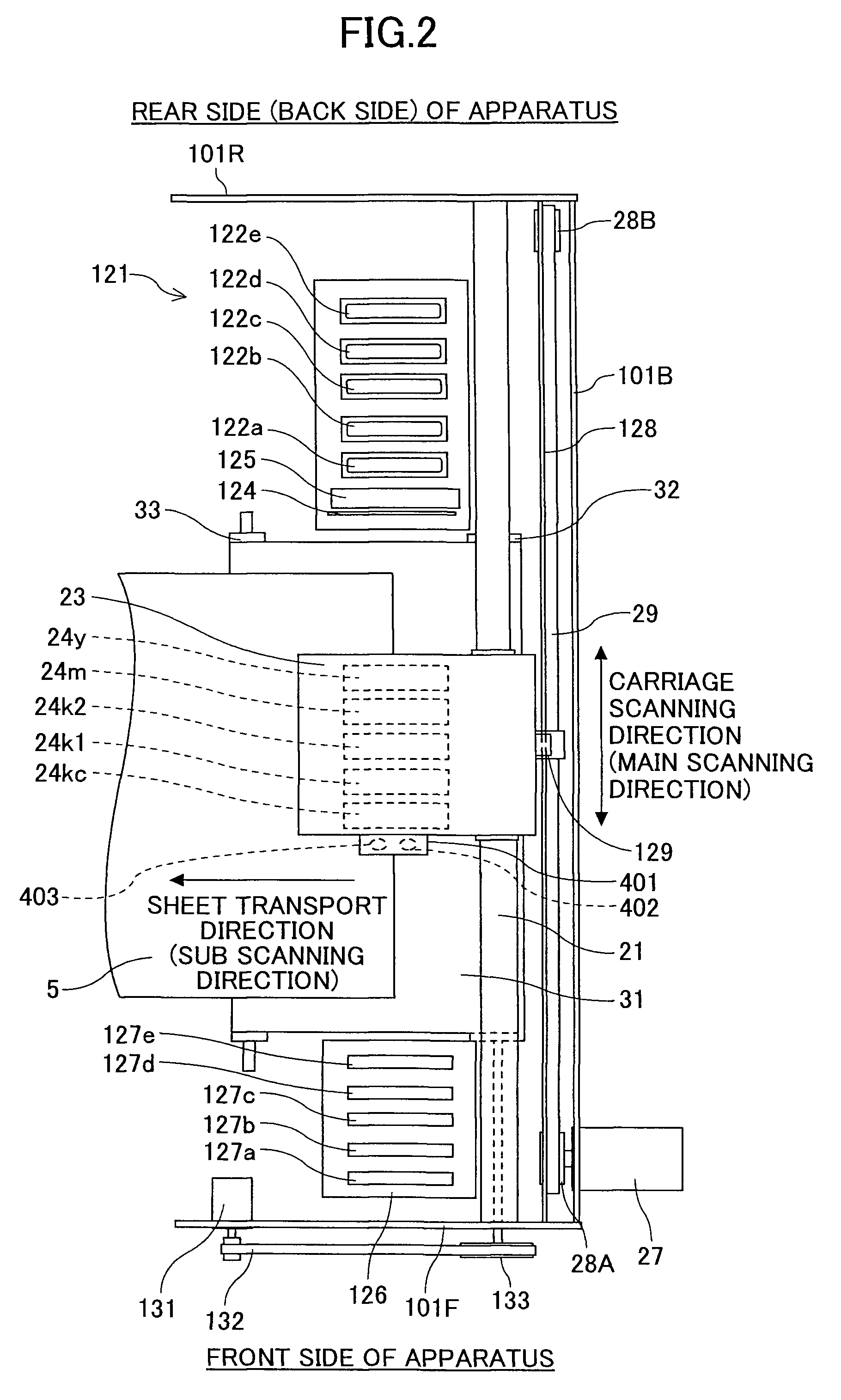
[0043]Exemplary embodiments of the present invention are described below with reference to the accompanying drawings. An example of an image forming apparatus of an embodiment of the present invention is described below with reference to FIGS. 1 through 5. FIG. 1 is a schematic configuration diagram illustrating the image forming apparatus. FIG. 2 is a plan view illustrating an image forming unit 2 and a sub scanning transport unit 3 of the image forming apparatus. FIG. 3 is a partly cut-away front view illustrating the image forming unit 2 and the sub scanning transport unit 3.

[0044]The image forming apparatus includes, in an apparatus main body 1 (i.e., in a casing), the image forming unit 2 that forms an image on a sheet (recording medium) 5 being transported and the sub scanning transport unit 3 that transports the sheet 5. In the image forming apparatus, sheets 5 are fed one by one from a feed unit 4 including a feed cassette 41 at the bottom of the apparatus main body 1. The s...


PUM


Abstract

A disclosed image forming apparatus includes a carriage on which a recording head is mounted that has a nozzle array where plural nozzles for ejecting droplets are arranged, the carriage being configured to be moved in a direction orthogonal to a nozzle arrangement direction; a transport belt facing the recording head and configured to transport a sheet; a print pattern forming unit configured to form a print pattern on the transport belt by causing at least the nozzles at opposing ends of the nozzle array to eject the droplets onto the transport belt while stopping the carriage; a reading unit configured to read the print pattern; a measuring unit configured to measure print positions of plural points of the print pattern in a direction orthogonal to the nozzle arrangement direction; and a detecting unit configured to detect an inclination of the recording head.

Description

BACKGROUND OF THE INVENTION[0001]1. Field of the Invention[0002]The present invention relates to an image forming apparatus including a recording head that ejects droplets.[0003]2. Description of the Related Art[0004]There are image forming apparatuses such as printers, facsimile machines, copying machines, plotters, and multifunction machines having functions of these devices. Inkjet recording apparatuses are known as liquid ejection recording type image forming apparatuses that use a recording head for ejecting ink droplets. The liquid ejection recording type image forming apparatuses form an image on a sheet by ejecting ink droplets from a recording head onto a sheet being transported. The image forming apparatuses of this type include serial type image forming apparatuses that form an image by ejecting droplets from a recording head moving in a main scanning direction and line type image forming apparatuses that form an image by ejecting droplets from a stationary recording head...

Claims


Application Information

Patent Timeline
IPC IPC(8): B41J29/38
CPCB41J29/393B41J29/38
Inventor NARUSE, SHINICHIROKAWABATA, KENICHINIIHARA, TAKAYUKIYORIMOTO, MAMORUMORINO, TETSUHAGIWARA, TAKUMI
Owner RICOH KK
Why Eureka
Try Eureka