Optical diffusing sheet, optical deflecting sheet, and transmission type screen

a technology of optical deflecting sheet and transmission type screen, which is applied in the field of optical deflecting sheet and optical deflecting sheet, can solve the problems of significant decrease in image quality, and deterioration of image quality of image projected on the screen, so as to prevent deterioration of image quality and prevent scattering of pieces of broken substra

Inactive Publication Date: 2009-07-30
DAI NIPPON PRINTING CO LTD
View PDF12 Cites 27 Cited by
  • Summary
  • Abstract
  • Description
  • Claims
  • Application Information

AI Technical Summary

Benefits of technology

[0010]The object of the present invention is to provide an optical diffusing sheet and an optical deflecting sheet that are capable of preventing a deterioration in an image quality which might be caused by warps of the sheets because of changes in the environment, and are capable of, even if a substrate is broken by an accident, preventing scattering of pieces of the broken substrate. The another object of the present invention is to provide a transmission type screen including the optical diffusing sheet and / or the optical deflecting sheet.
[0011]An optical diffusing sheet according to the present invention is an optical diffusing sheet for use in a transmission type screen that emits imaging light projected from an incident side to an emergent side, comprising: a highly rigid substrate layer with a light-transmissibility and a high rigidity; and two or more layers laminated on the highly rigid substrate layer, the layers including at least a pair of anti-scattering layers disposed on opposite sides of the highly rigid substrate layer for preventing scattering of the highly rigid substrate layer; wherein at least one layer of the two or more layers includes an optical diffusing element that diffuses imaging light.
[0012]According to the optical diffusing sheet of the present invention, due to the highly rigid substrate layer with a light-transmissibility and a high rigidity, it is possible to restrain a warp of the optical diffusing sheet, which might be caused by changes in the environment such as temperature and humidity, and also restrain a flexure of the optical diffusing sheet, which might be caused by its own weight. Moreover, since the anti-scattering layers are formed on opposite sides of the highly rigid substrate layer, even when the highly rigid substrate layer is broken by an accident such as a collision, scattering of pieces of the broken substrate can be prevented.

Problems solved by technology

When imaging light is projected on the transmission type screen under such conditions, there arises a problem of significant decrease in an image quality, such as defocusing, a deterioration in reproducing colors, a double image, and a distorted image.
Thus, only a small warp or a float generated in the screen considerably deteriorates an image quality of an image projected on the screen.
In addition, as compared with a small-sized screen, a large-sized transmission type screen involves a problem in that deterioration in an image caused by a warp or a float, which has been generated by changes in the environment, is more conspicuous.
However, this transmission type screen has a problem in that, since a frontmost surface (surface closest to an observation side) of an emergent side of the transmission type screen is provided by the glass substrate, if the glass substrate is damaged by an accident or the like, pieces of broken glass are scattered.
However, there exist the following problems.
That is to say, it is not easy to mix a diffusing agent in a glass substrate, which increases the manufacturing cost of the glass substrate.
In addition, mixture of a diffusing agent undesirably makes the glass substrate fragile, whereby the glass substrate is liable to be broken.
However, when a Fresnel lens sheet having a Fresnel lens disposed on its emergent side (glass-substrate side) is used, this is disadvantageous in that the Fresnel lens is rubbed by the glass substrate which tightly contacts a surface on which the Fresnel lens is disposed.
However, there are the following problems.
That is to say, it is not technically easy to directly form a Fresnel lens on a glass substrate, which leads to increase in the manufacturing cost of the glass substrate.
Further, it is only one surface of the glass substrate that is protected by the plastic sheet, while the opposite surface of the glass substrate with the Fresnel lens formed thereon is not protected.
Thus, if the glass substrate is broken by an accident or the like, pieces of the broken glass substrate are scattered, or the Fresnel lens is scratched or stained by the pieces.
Furthermore, there is another problem in that, since a concave portion of the Fresnel lens is concentrically subjected to a stress, the Fresnel lens can be easily broken.
However, in the screen disclosed in this document wherein a frontmost surface is provided by the glass substrate, there is a problem in that, if the glass substrate is broken, pieces of the broken glass substrate are scattered.

Method used


Image

  • Optical diffusing sheet, optical deflecting sheet, and transmission type screen
  • Optical diffusing sheet, optical deflecting sheet, and transmission type screen
  • Optical diffusing sheet, optical deflecting sheet, and transmission type screen

Examples


first embodiment

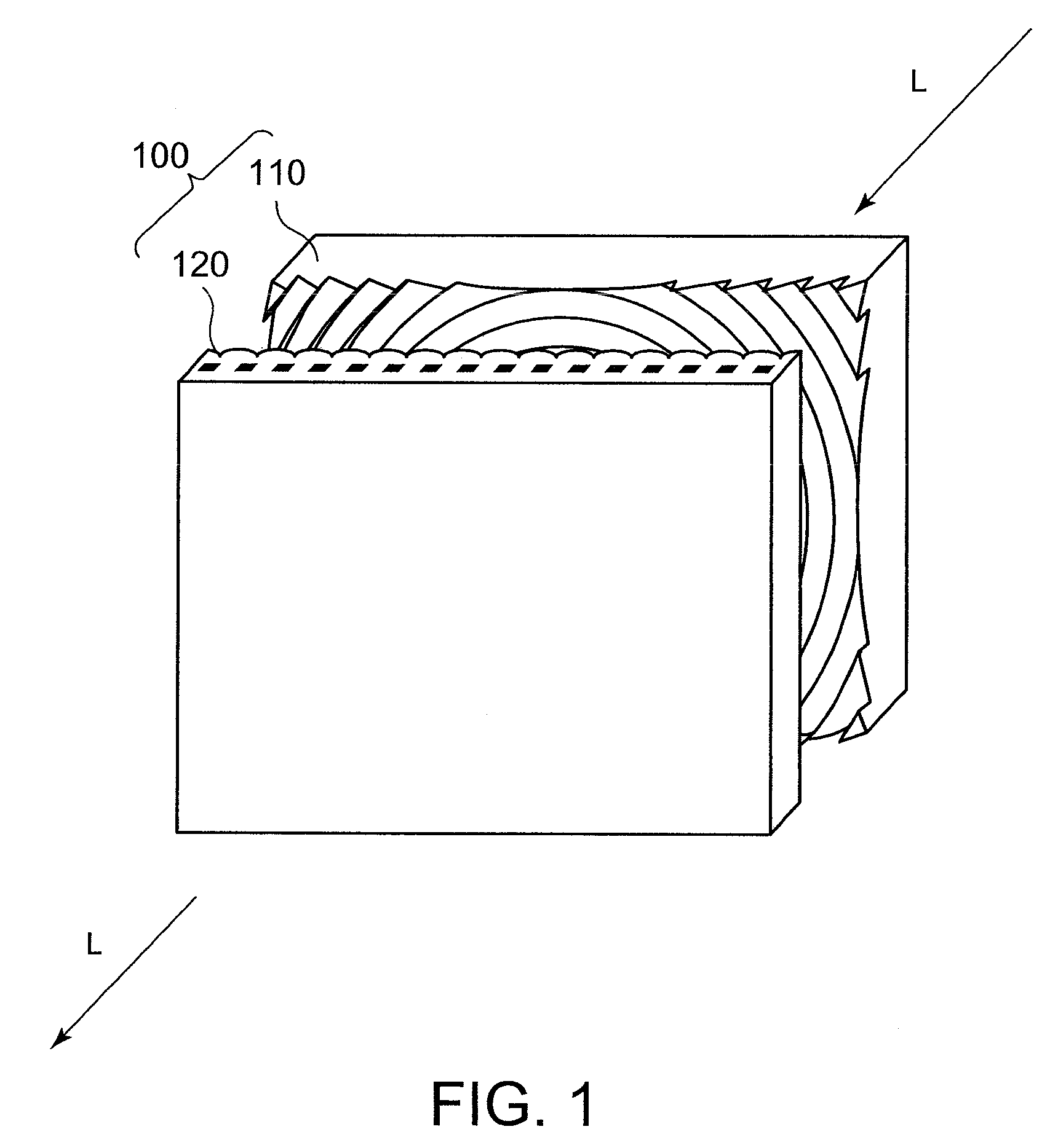
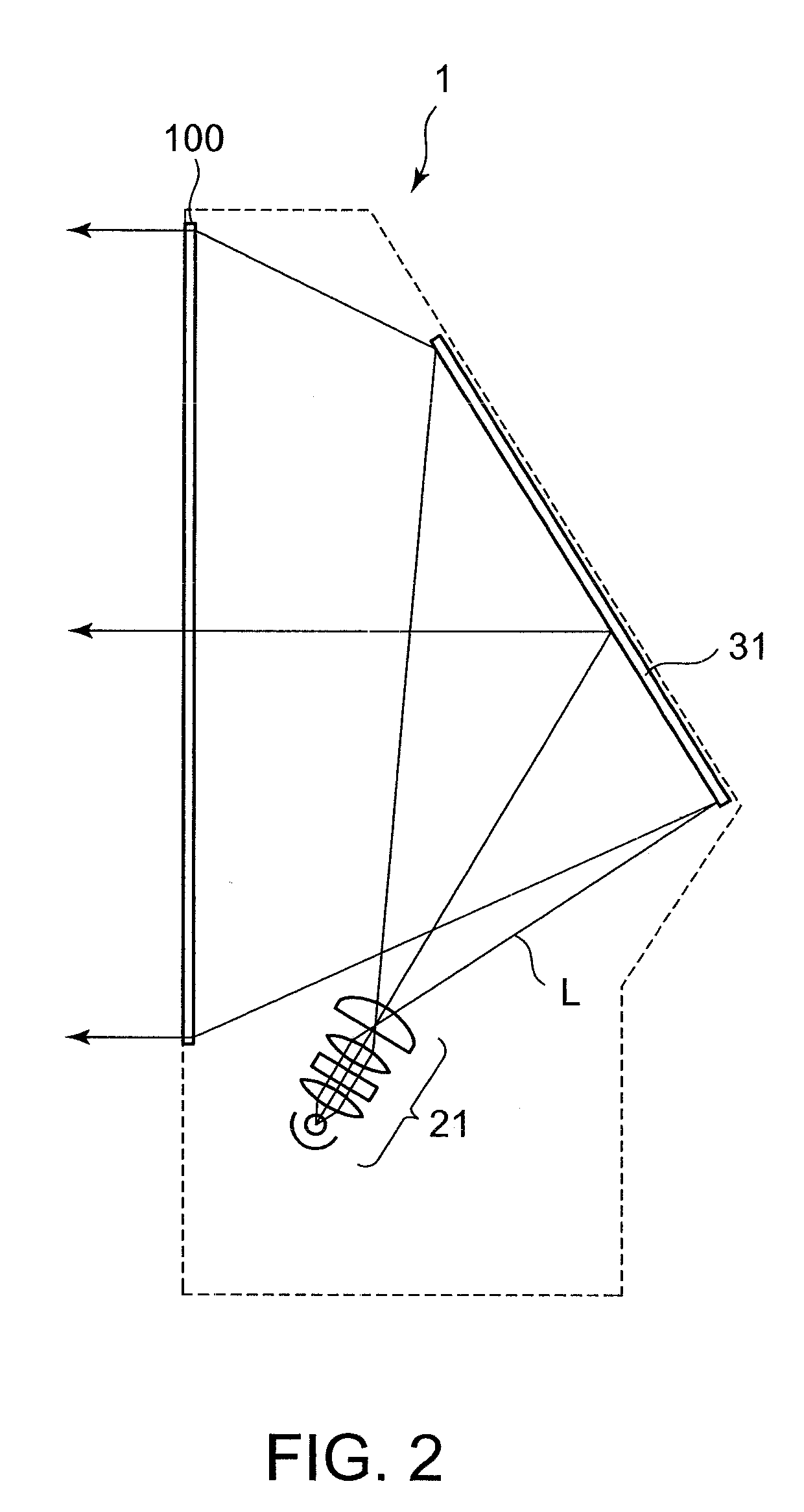
[0060]FIG. 1 is a view of a first embodiment of a transmission type screen according to the present invention. FIG. 2 is a sectional view of a rear projection television using the first embodiment of the transmission type screen.

[0061]As shown in FIG. 1, the transmission type screen 100 in the first embodiment includes an optical deflecting sheet disposed on an incident side (light source side) of imaging light L, and an optical diffusing sheet disposed on an emergent side (observation surface side) of the imaging light L. The transmission type screen 100 is positioned on an image-formation surface of the imaging light L. In this transmission type screen, the optical diffusing sheet is formed as a lenticular lens sheet having a lenticular lens, while the optical deflecting sheet is formed as a Fresnel lens sheet having a Fresnel lens.

[0062]As shown in FIG. 2, the rear projection television 1 is an image display device of rear-projection type that includes: the transmission type scre...

second embodiment

[0097]FIG. 11 is a second embodiment of the transmission type screen according to the present invention. As shown in FIG. 11, the transmission type screen 400 in the second embodiment includes an optical deflecting sheet disposed on an incident side of imaging light L, and an optical diffusing sheet 420 disposed on an emergent side of the imaging light L. The transmission type screen 400 in the second embodiment is used in the rear projection television 1 shown in FIG. 2, similar to the transmission type screen 100 described in the first embodiment.

[0098]The optical deflecting sheet 410 in this transmission type screen is formed as a Fresnel lens sheet having a Fresnel lens, similar to the first embodiment. Meanwhile, the optical diffusing sheet 420 is formed of a sheet-like member which is different from that of the first embodiment, as described below.

[0099]FIG. 12 is a schematic view of a layer structure of the second embodiment of the transmission type screen.

[0100]The Fresnel l...

third embodiment

[0118]FIG. 15 is a view of a third embodiment of the transmission type screen according to the present invention.

[0119]FIG. 16 is a sectional view of a rear projection television using the third embodiment of the transmission type screen.

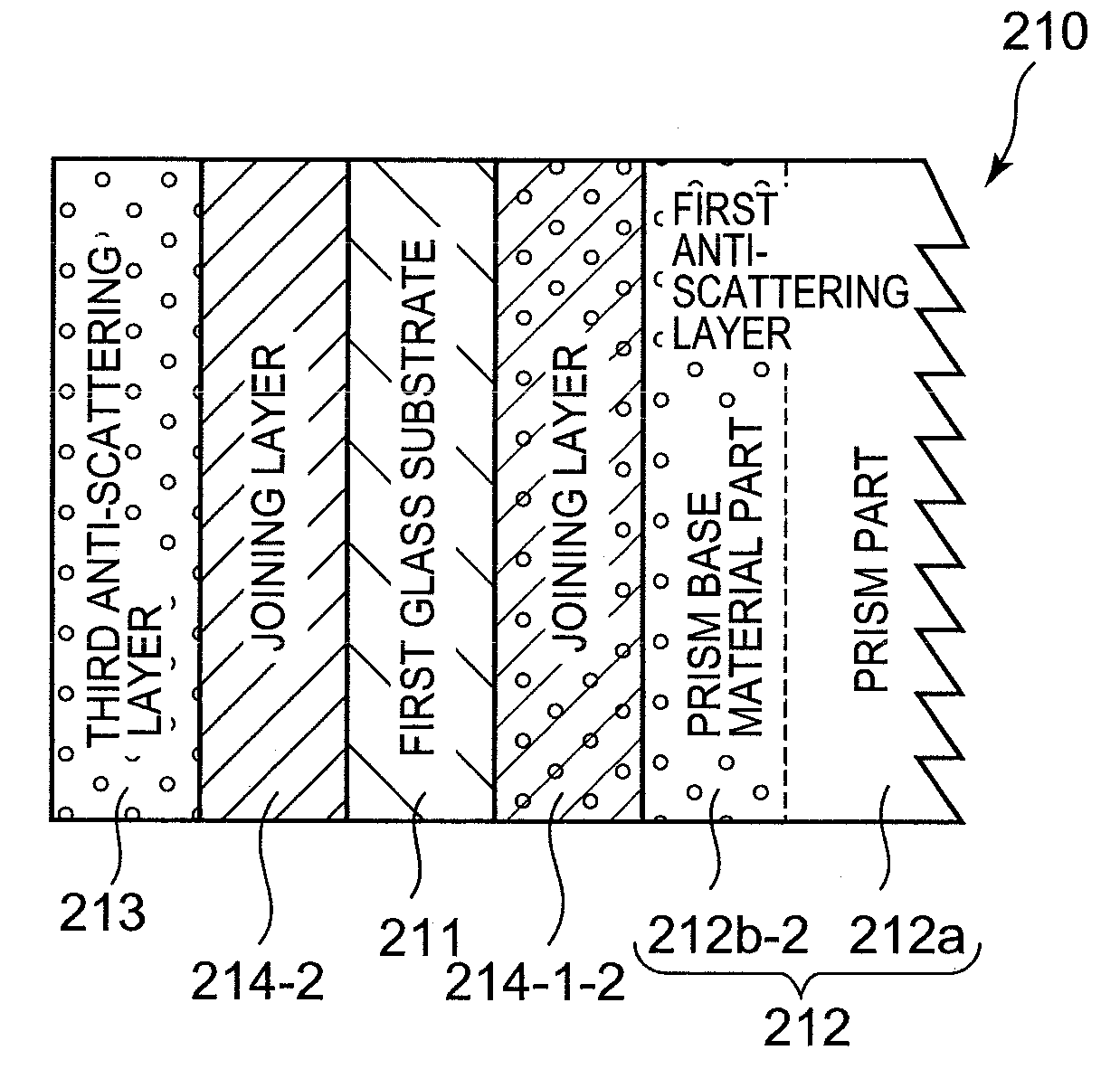
[0120]As shown in FIG. 15, the transmission type screen 200 in the third embodiment includes an optical deflecting sheet 210 disposed on an incident side (light source side) of imaging light L, and an optical diffusing sheet 220 disposed on an emergent side (observation surface side) of the imaging light L. A combination of the optical deflecting sheet and the optical diffusing sheet is used, as the transmission type screen, in a rear projection television 2 shown in FIG. 16.

[0121]In this transmission type screen, the optical diffusing sheet 220 is formed as the lenticular lens sheet having the lenticular lens used in the first embodiment. Meanwhile, the optical deflecting sheet 210 is formed as a prism sheet having a prism part (optical deflecting ...


PUM


Abstract

An optical diffusing sheet is provided, which prevents deterioration in image quality which might result from warping of the sheets due to environmental changes, and is capable of, even if a substrate is broken by an accident, preventing scattering of pieces of the broken substrate. An optical diffusing sheet is used in a transmission type screen that emits imaging light projected from an incident side to an emergent side. The optical diffusing sheet includes a highly rigid substrate layer with a light-transmissibility and a high rigidity, and a plurality of layers laminated on the highly rigid substrate layer. The plurality of layers includes at least a pair of anti-scattering layers disposed on opposite sides of the highly rigid substrate layer for preventing scattering of the highly rigid substrate layer. At least one layer of the two or more layers includes an optical diffusing element that diffuses imaging light.

Description

TECHNICAL FIELD[0001]The present invention relates to an optical diffusing sheet and an optical deflecting sheet for use in a transmission type screen that emit imaging light projected from a light source to an emergent side, and to a transmission type screen that uses at least one of the optical diffusing sheet and the optical deflecting sheet.BACKGROUND ART[0002]In a rear-projection type display device that projects imaging light on a screen from its rear, a transmission type screen has been used as a screen for displaying enlarged imaging light projected thereon. Generally, this transmission type screen has been used by combining an optical deflecting sheet (e.g., Fresnel lens sheet) that collimates imaging light projected from a light source by deflecting the same in parallel light rays, and emits the light to an observation surface side, and an optical diffusing sheet (e.g., lenticular lens sheet) that diffuses imaging light.[0003]The optical deflecting sheet or the optical dif...

Claims


Application Information

Patent Timeline
Patent Type & Authority Applications(United States)
IPC IPC(8): G03B21/62G02B5/02
CPCG02B5/0242G03B21/625G02B5/0278
Inventor KODAMA, DAIJIROKASHIWAGI, TSUYOSHIKATO, KEI
Owner DAI NIPPON PRINTING CO LTD
Why Eureka
Try Eureka