

Child-resistant lighter
a lighter, child-resistant technology, applied in the direction of fuel lighters, combustion processes, lighting and heating equipment, etc., can solve the problem of user's hardness and exertion of for
- Summary
- Abstract
- Description
- Claims
- Application Information
AI Technical Summary
Benefits of technology
Problems solved by technology
Method used
Image

Examples
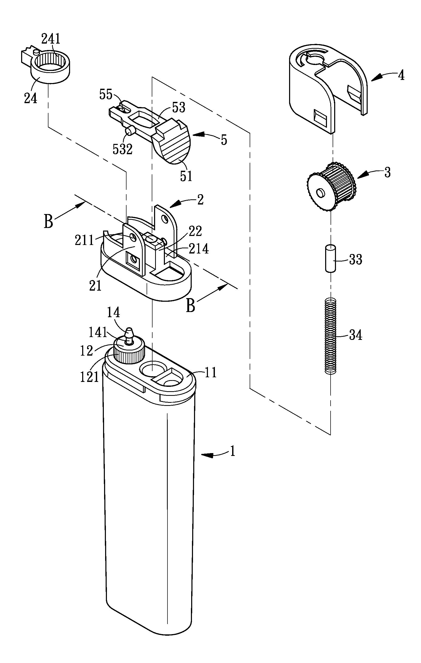
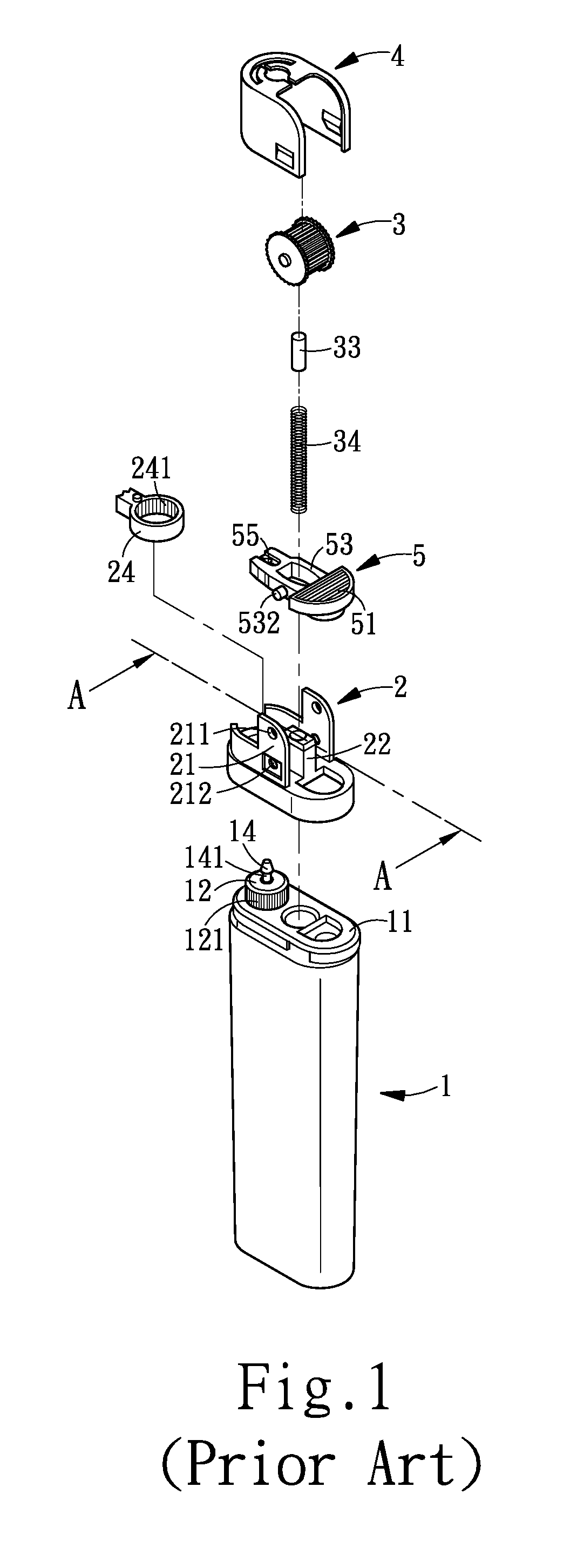
first embodiment
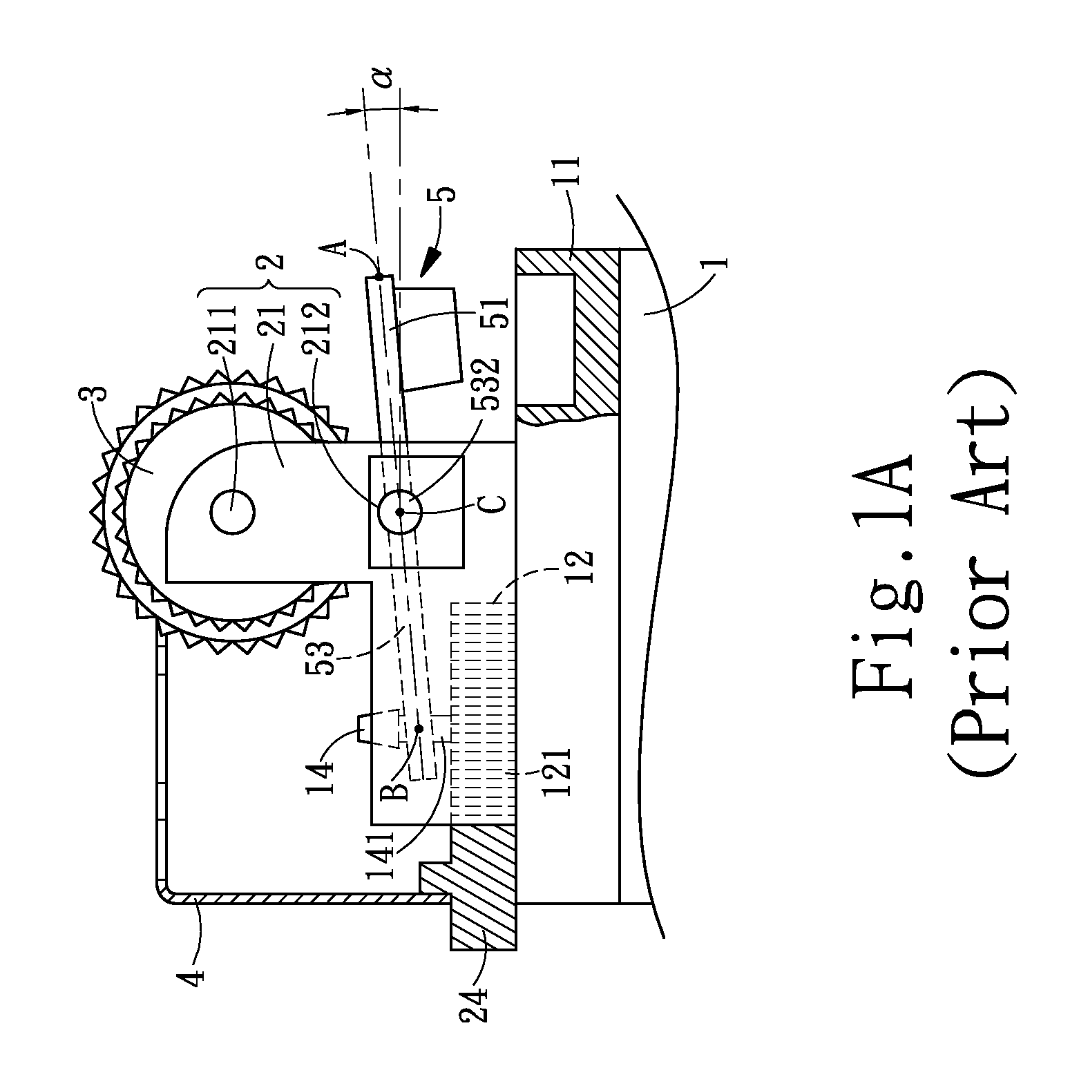
[0028]As shown FIG. 2A, in the invention, the cross-section of the pressing part appears a rhombus shape.
second embodiment
[0029]As shown FIG. 3A, in the invention, the cross-section of the pressing part appears a rectangular shape with a chamfered vertex angle.
third embodiment
[0030]As shown FIG. 4A, in the invention, the cross-section of the pressing part appears a new-moon shape.
[0031]As shown again in FIG. 2A, FIG. 3A, and FIG. 4A, the angle α being the horizontal upward slant angle is within a range of 10°≦α≦20° and the slant surface of the pressing part makes an angle θ with respect to the lever (5) which makes a downward slant angle θ-α. If the exerting force of the user to exert force on the pressing part by his / her thumb is P, then the effective exerting force acting on the lever is P cos θ where the effective range of the angle θ is 27°≦θ≦60°, namely, the minimum and maximum value of θ are 27° and 60° respectively, thereby the range of effective exerting force is 0.5 P≦P cos θ≦0.9 P. In other words, the exerting force P of the user to press the pressing part and the file wheel by his / her thumb is reduced into 0.9P to 0.5P. As a result, the lighter of the invention is capable of protecting the children from causing fire accident to achieve the eff...
PUM
 Abstract
Description
Claims
Application Information