Flap valve

a technology of flap valve and valve body, which is applied in the field of flap valve, can solve the problems of valves with extremely poor sealing qualities, valves that are not generally mosquito-proof, and valves that are unsuitable for a number of potential installations

Inactive Publication Date: 2005-05-05
WADE RODNEY GEORGE
View PDF11 Cites 25 Cited by
  • Summary
  • Abstract
  • Description
  • Claims
  • Application Information

AI Technical Summary

Benefits of technology

[0005] It is therefore a primary object of the present invention to provide a flap valve which obviates or at least minimises these disadvantages and provides the public with a useful alternative.

Problems solved by technology

Such valves have extremely poor sealing qualities and are not generally mosquito proof.
This makes the valves unsuitable in a number of potential installations such as the overflow outlet on rain water storage tanks.

Method used


Image

  • Flap valve
  • Flap valve
  • Flap valve

Examples


Embodiment Construction

[0022] In all the drawings, like reference numerals refer to like parts.

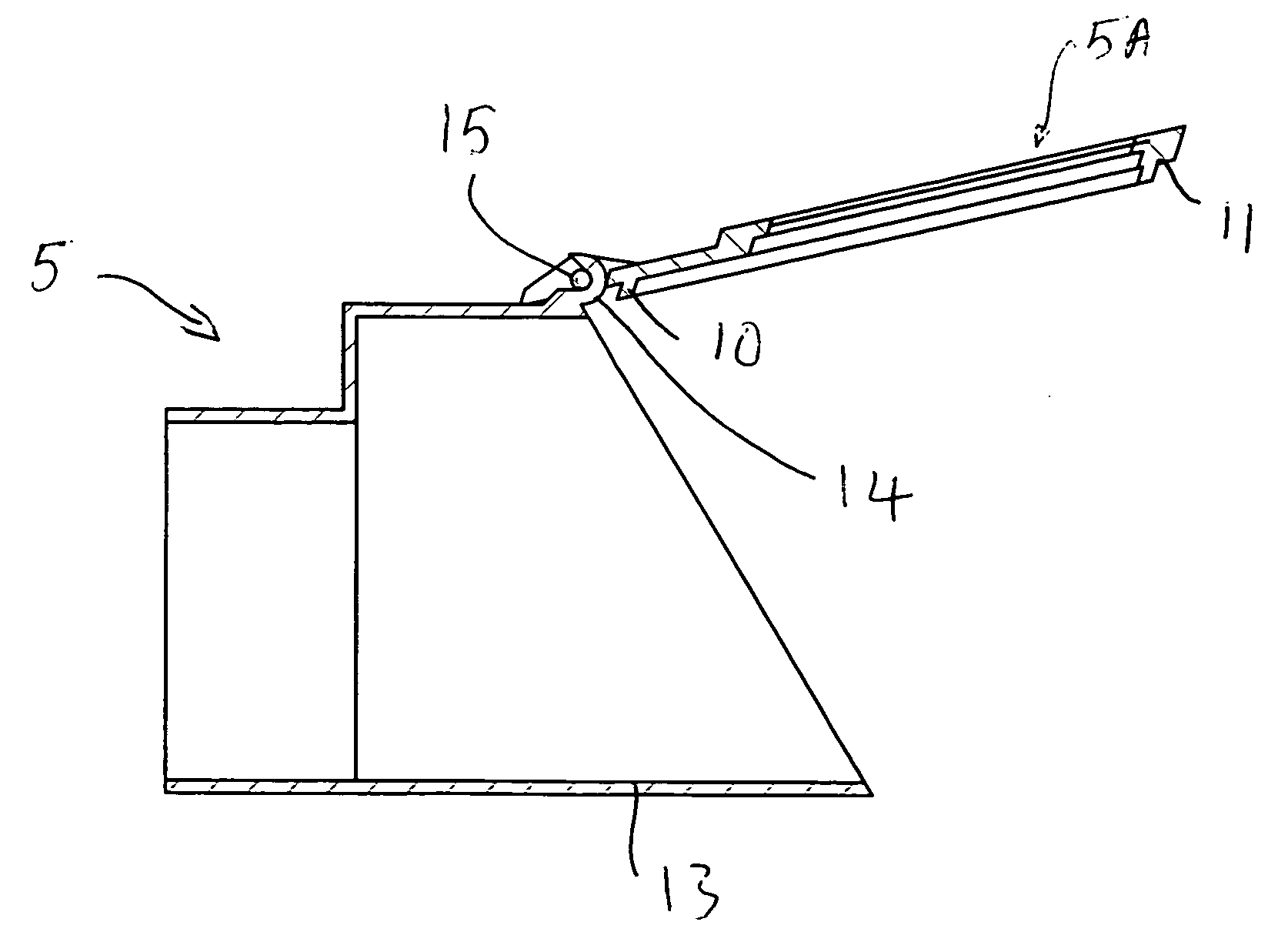
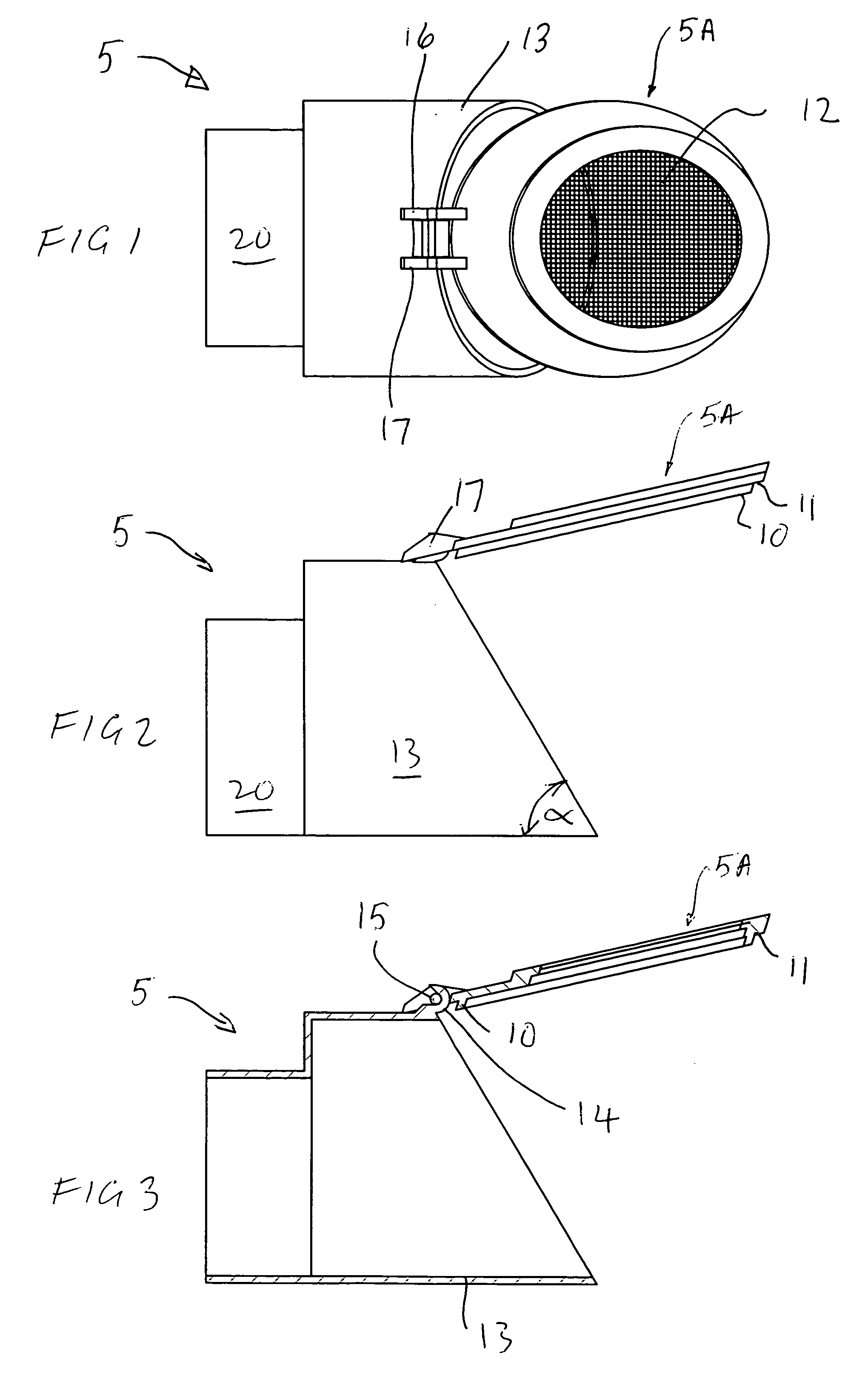
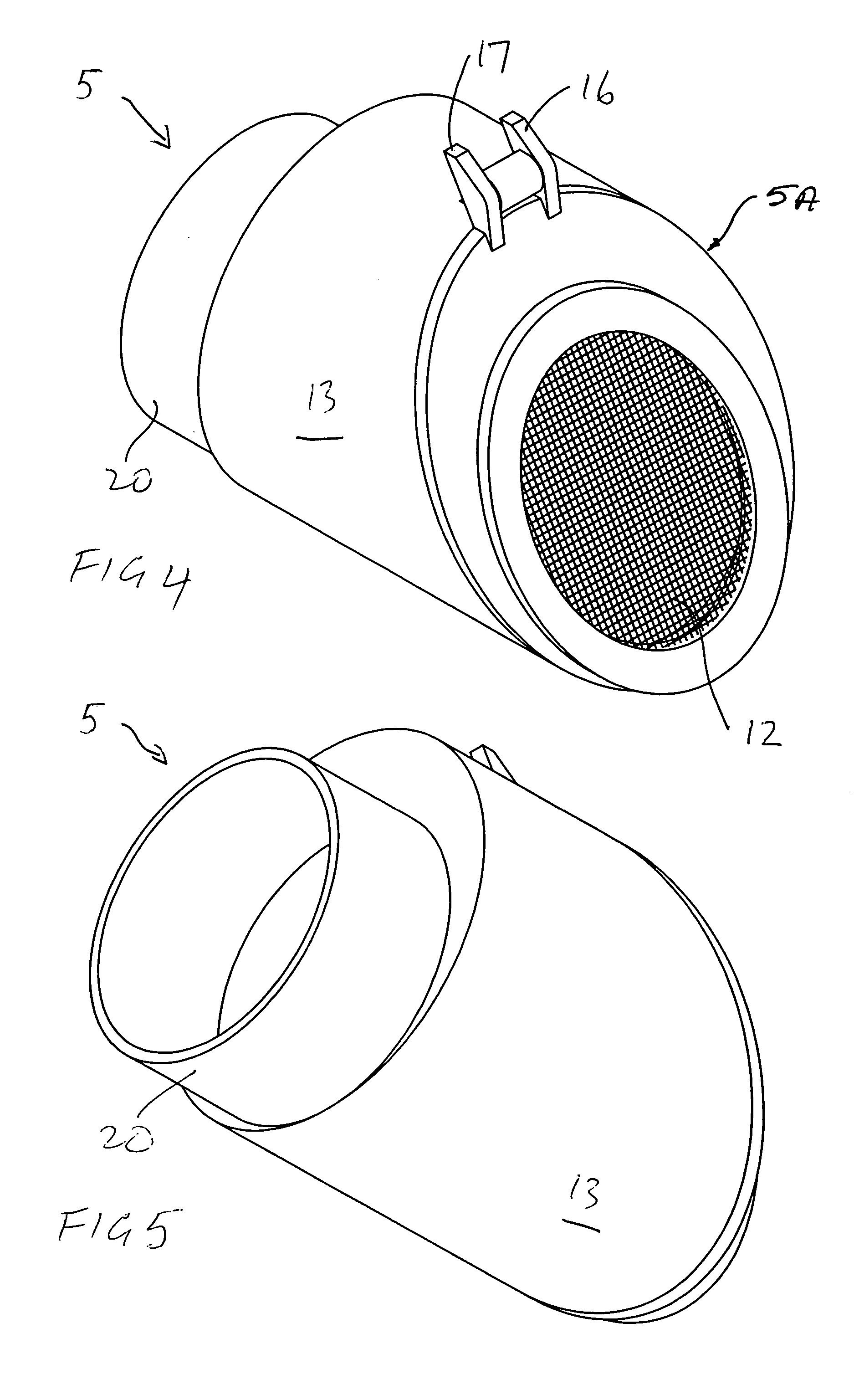
[0023] The flap valve 5 as depicted has a flap 5A with an elliptical annular extension 10 with an integral flange 11 formed from injected moulded polyvinylchloride plastics material.

[0024] A mesh 12 of 304 grade 955 micron aperture stainless steel formed from 0.315 mm diameter wire is embedded in the flange during the production of the annular extension / flange, in a one-step operation.

[0025] The flap 5A is connected to an end-piece 13 of a first spigot, also formed from polyvinylchloride plastics material. The end-piece is dimensioned for slipping over the end of an over-flow or like pipe using a conventional pcv adhesive. The end-piece is tapered adjacent the flap 5A to an angel a of approximately 60° C.

[0026] The top outer region of the end-piece includes an integrally moulded ridge 14 with partial internal bore to form a hook which accommodates a pivot pin 15. The pivot pin enables the flap 5A to be conne...


PUM


Abstract

A flap valve is disclosed having a first spigot and a closure flap with an annular extension adapted to snugly fit within an outlet end of the first spigot and a flange integral with the annular extension adapted to circumscribe the outlet end. The flap valve having a second spigot of smaller diameter than the first spigot forming an extension to the first spigot.

Description

BACKGROUND OF THE INVENTION [0001] This invention relates to flap valves and, in particular, to flap valves for water storage tanks and similar installations where venting is desirable. [0002] Flap valves are incorporated on pipe outlets to enable liquid within the pipe to flow out but to prevent vermin such as cockroaches and other insects from entering the pipe when there is no flow of liquid through the pipe. [0003] Existing flap valves comprise a planar disc of plastics or like material which is pivotally connected to the upper outer edge of a sleeve which is fitted to the pipe at it's outlet. Such valves have extremely poor sealing qualities and are not generally mosquito proof. This makes the valves unsuitable in a number of potential installations such as the overflow outlet on rain water storage tanks. [0004] Existing flap valves are constructed such that the sleeve is able to be fitted to an outlet pipe of one particular diameter. OBJECTS OF THE INVENTION [0005] It is there...

Claims


Application Information

Patent Timeline
Patent Type & Authority Applications(United States)
IPC IPC(8): E03B3/03E03B7/08E03B11/02F16K15/03F16K24/04F16K24/06F16L55/07
CPCF16K15/03Y10T137/7902
Inventor WADE, RODNEY GEORGE
Owner WADE RODNEY GEORGE
Why Eureka
Try Eureka