Venturi device and method
- Summary
- Abstract
- Description
- Claims
- Application Information
AI Technical Summary
Benefits of technology
Problems solved by technology
Method used
Image
Examples
embodiment 110
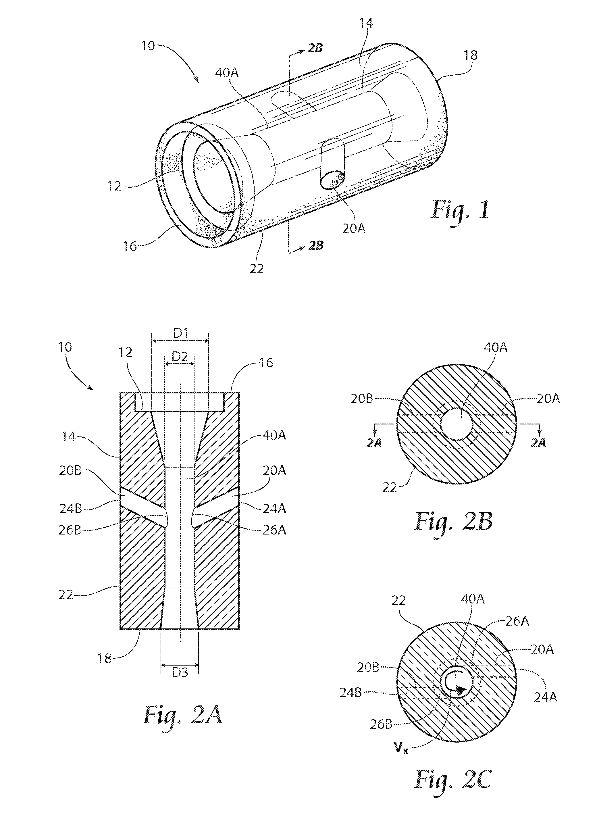
[0040]The embodiment 110 illustrated in FIGS. 7 and 8 provides an alternative device for more easily aerating wine from a wine box 50 or other type of bladder container in conjunction with a dispensing valve 32A. The central bore 40B having relatively larger diameters D′1, D′2, D′3, along with the placement, of passage 20C, permits an increased flow rate if so desired. An example of non-limiting approximate relative diameters workable with the device 110 includes D′1=0.48, D′2=0.203, and D′3=0.30, however, it is to be understood that the actual diameters D′1, D′2, D′3 may be varied, without departing from the invention. Further, the tapered end portion 48 of the device 110 promotes facile and complete wine dispensation after the dispensing valve 32A (see FIG. 6) is closed. The tapered portion 48 serves to direct residual mixed fluid 36 remaining in the central bore 40B along the third, diameter D′3, to thereby collect any residual fluid 36 at the tapered portion 48 and allowing any ...
embodiment 210
[0041]Another embodiment of the venturi device 210 is shown in FIGS. 9-11C. Similarly to the devices 10, 110 shown and discussed with reference to FIGS. 1-6 and 7 and 8, the device 210, shown in FIGS. 9 and 10, includes a body 14 having a first end 16, a second, end 18, an outer periphery 22, and at least one induction passage 20A. The device 210 further includes a second end 18 having an elongated, tapered end portion 48. However, and as may be seen particularly in FIG. 11A, the device 210 includes a central bore 40C having a first diameter D″1 and a second diameter D″2, wherein the first and second diameters D″1, D″2 are of substantially the same size. As shown, the device 210 may further include induction passages 20C and 20D. As viewed particularly in FIG. 12, the arrangement of alternative embodiment 210 is well suited, to be integrally molded with the dispensing valve 32A due to manufacturing and molding considerations. For example, with the first and the second diameters D′1,...
embodiment 310
[0043]Turning now to FIG. 13, another embodiment 310 is shown. As illustrated, the device 310 may be envisioned for use in combination with a beverage dispensing nozzle 52 and for use with an alternative dispenser 32B. When used in the manner shown in FIG. 13, the device 310 preferably includes an external attachment means, such as the securing mechanism 42 shown. Similar to the devices 10, 110, 210 discussed, previously, the device 310 shown in FIG. 13 includes a body 14 with a first end 16 and a second end 18, mating interface 12 at the first end 16, and an elongated tapered end portion 48 at the second end 18, and at least one induction passage 20. However, as may be seen in FIG. 13, the embodiment 310 further includes a securing mechanism 42 to attach the device 310 to an alternative dispenser 32B, such as the nozzle 52 shown. As illustrated, the device 310 preferably includes a portion 52 of the first end 16 configured to provide an interface between a portion of the outer peri...
PUM
| Property | Measurement | Unit |
|---|---|---|
| Pressure | aaaaa | aaaaa |
| Diameter | aaaaa | aaaaa |
| Size | aaaaa | aaaaa |
Abstract
Description
Claims
Application Information
 - R&D
- Intellectual Property
- Life Sciences
- Materials
- Tech Scout
- Unparalleled Data Quality
- Higher Quality Content
- 60% Fewer Hallucinations
Browse by: Latest US Patents, China's latest patents, Technical Efficacy Thesaurus, Application Domain, Technology Topic, Popular Technical Reports.
© 2025 PatSnap. All rights reserved.Legal|Privacy policy|Modern Slavery Act Transparency Statement|Sitemap|About US| Contact US: help@patsnap.com


