Patient Ventilating And Aspirating System

a patient ventilating and aspiration technology, applied in the field of catheter tube connectors, can solve the problems of contaminating caregivers, unable to clear the secretions in the lungs and airways of patients who are ventilated in this manner, and exposed to the atmosphere, so as to improve the usefulness of the system

Active Publication Date: 2008-11-06
FISHER & PAYKEL HEALTHCARE LTD
View PDF45 Cites 23 Cited by
  • Summary
  • Abstract
  • Description
  • Claims
  • Application Information

AI Technical Summary

Benefits of technology

[0004]There are a number of medical procedures that require placement of a tracheostomy or endotracheal tube into the windpipe to deliver air directly into the lungs. A patient who is ventilated in this manner cannot clear secretions collecting in their lungs and airways by themselves. To overcome this problem, a sterile flexible aspirating tube is inserted into the patient via the tracheostomy or endotracheal tube. The aspirating tube is used in conjunction with an external vacuum source to create suction and help clear the secretions. In the method of secretion removal known as the open suction system, the aspirating tube is disposed of immediately after use as it will have become contaminated by the pathogens and bacteria that live in the patient's airway, and once it

Problems solved by technology

A patient who is ventilated in this manner cannot clear secretions collecting in their lungs and airways by themselves.
In the method of secretion removal known as the open suction system, the aspirating tube is disposed of immediately after use as it will have become contaminated by the pathogens and bacteria that live in the patient's airway, and once it is removed from the patient's airway the tube will be exposed to atmosphere, with the risk of contaminating caregivers.
The device disclosed has the disadvantage that the aspirating catheter tube is exposed to the atmosphere before being pushed into the trachea via the tracheostomy tube.
A further disadvantage of this system is that the resistance of the tube passing through and over the seal can be high, and can cause the patient some discomfort as the tracheostomy tube and other fittings are inadvertently moved and twisted in order to overcome this resistance.
The device disclosed has the disadvantage that the ventilator tube is unsealed when the connector is released in order to carry out routine cleaning or maintenance, o

Method used


Image

  • Patient Ventilating And Aspirating System
  • Patient Ventilating And Aspirating System
  • Patient Ventilating And Aspirating System

Examples


Embodiment Construction

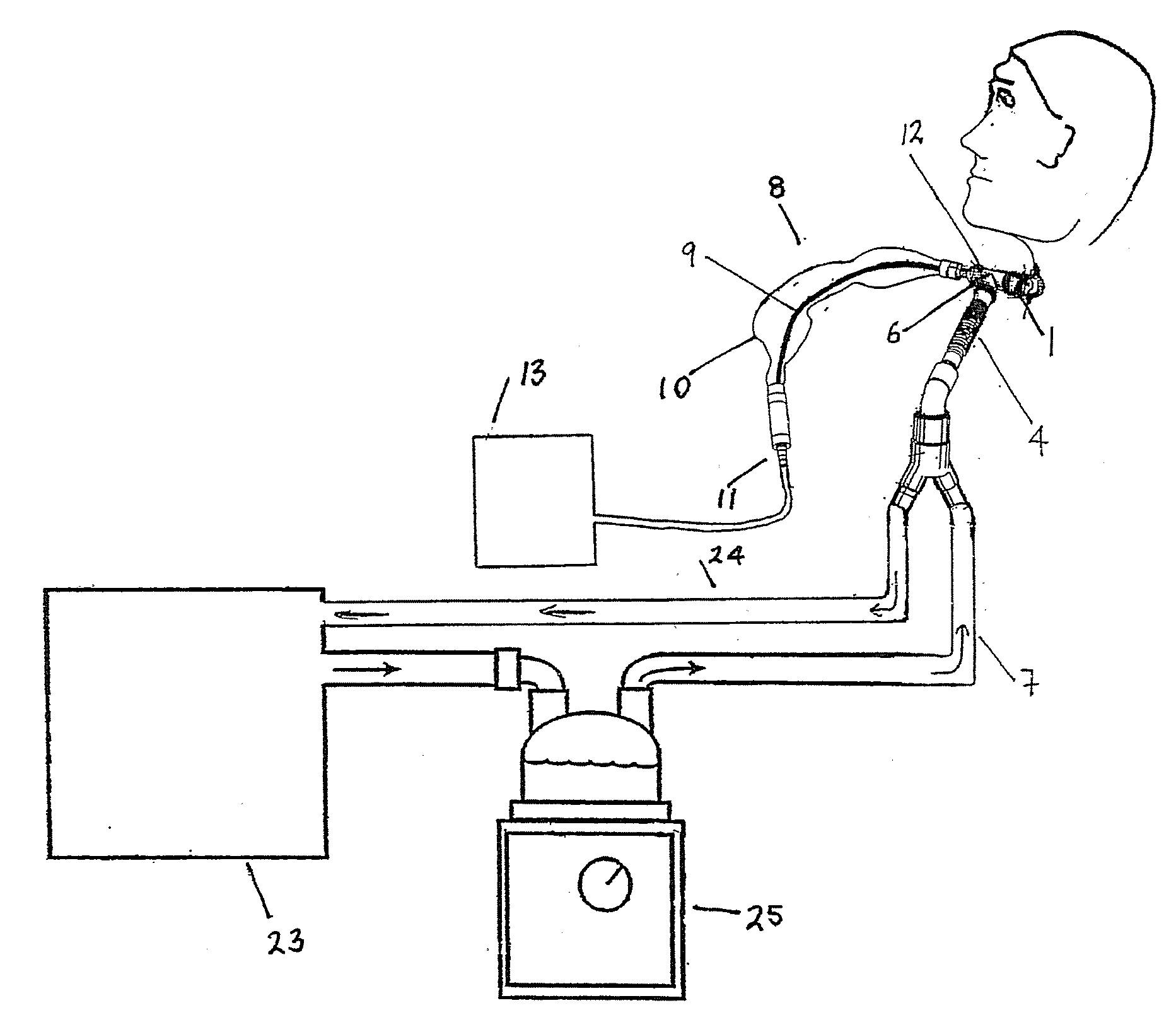
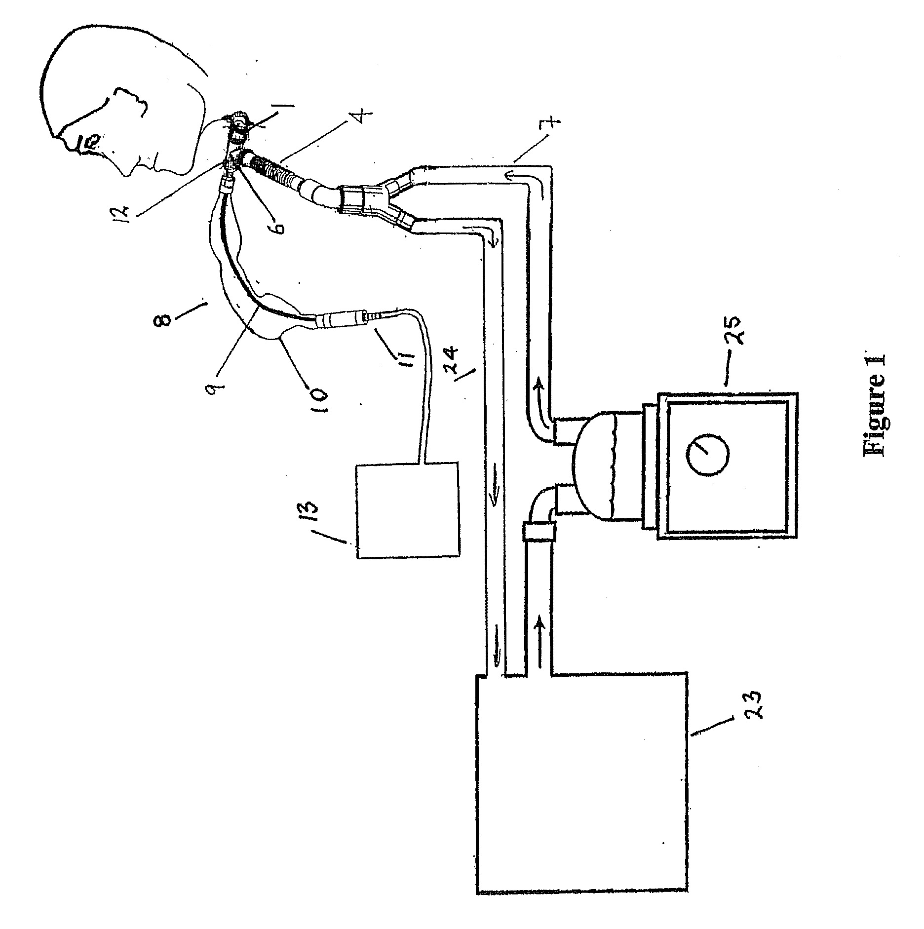
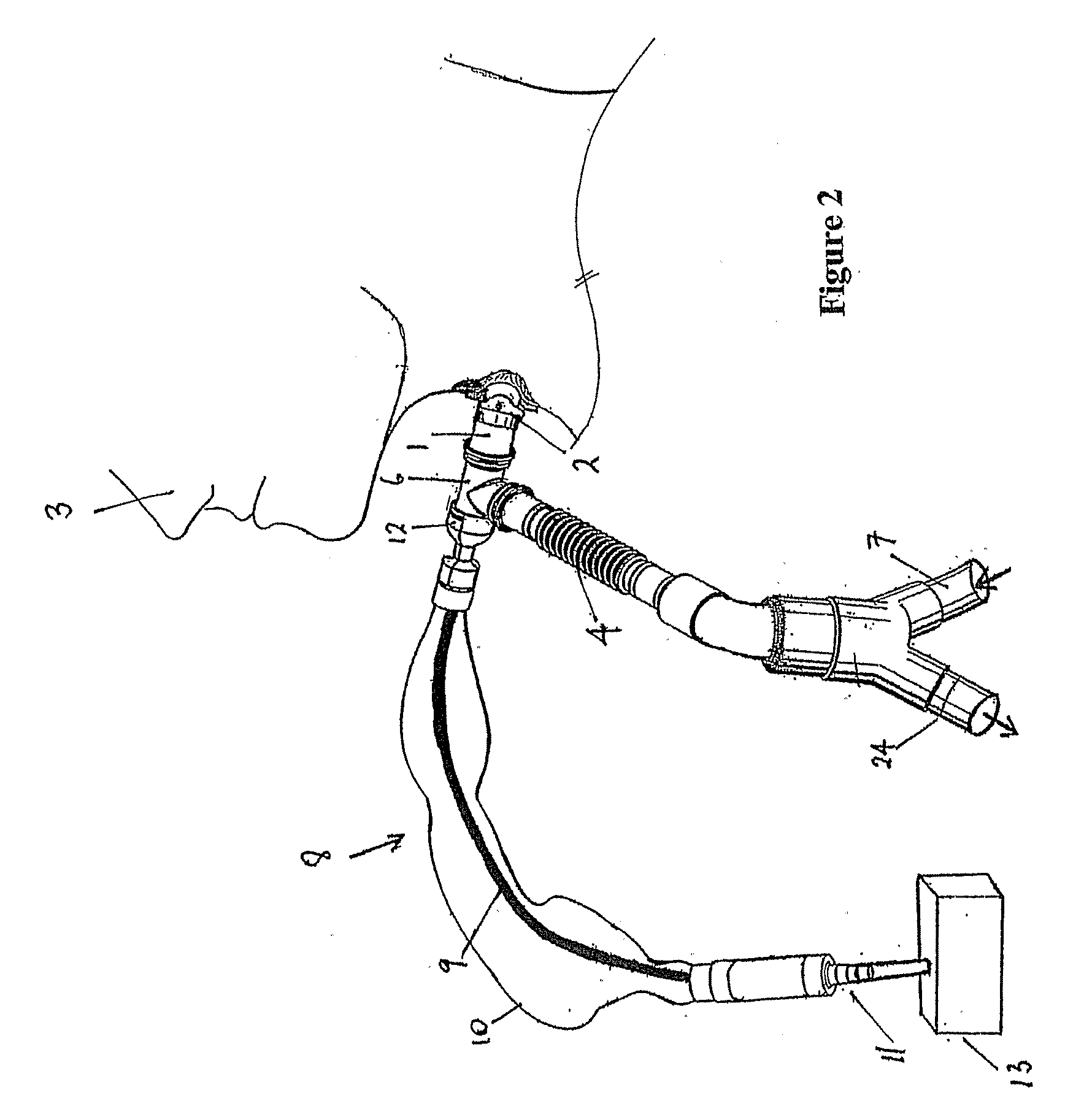
[0030]The present invention consists of several separate pieces that are fitted together to form a system to ventilate and aspirate a patient 3. The system comprises a tracheostomy or endotracheal connector 1 (hereinafter “patient connector 1”) which in use attaches to the tracheostomy or endotracheal fitting 2 located in the neck or throat of a patient 3. In the Figures the patient is only shown with tracheostomy not an endotracheal fitting and tube. An elbow connector 6 and catheter tube 4 are connected together to form a catheter mount. The elbow connector 6 is attached to the patient connector 1. An aspirating assembly 8 is also provided that is attached to the elbow connector 6. The catheter tube 4 is effectively a piece of tubing that connects the elbow connector 6 to the ventilator system that supplies gases to the patient's airways.

[0031]In the preferred embodiment described, the patient has undergone surgery and has had a tracheostomy or endotracheal fitting 2 inserted into...


PUM


Abstract

A patient ventilating (23) and aspirating system (8) is disclosed that has a suction tube (9) and connector (6) for connecting to a catheter mount that has a scaled passageway (15). The catheter mount passageway (15) is sealed with an elastomeric seal (16) including a perforation or slit (17). A connector (12) with a piercing member is associated with the suction tube (9). When the connector is attached to the catheter mount the piercing member (20) pierces the seal (16) such that the suction tube (9) can pass through the connector (6) and catheter mount.

Description

BACKGROUND OF THE INVENTION[0001]1. Field of the Invention[0002]This invention relates to a catheter tube connector, and in particular, but not solely to a catheter tube connector for a suction system used with a tracheostomy or endrotracheal patient ventilation system.[0003]2. Summary of the Prior Art[0004]There are a number of medical procedures that require placement of a tracheostomy or endotracheal tube into the windpipe to deliver air directly into the lungs. A patient who is ventilated in this manner cannot clear secretions collecting in their lungs and airways by themselves. To overcome this problem, a sterile flexible aspirating tube is inserted into the patient via the tracheostomy or endotracheal tube. The aspirating tube is used in conjunction with an external vacuum source to create suction and help clear the secretions. In the method of secretion removal known as the open suction system, the aspirating tube is disposed of immediately after use as it will have become co...

Claims


Application Information

Patent Timeline
IPC IPC(8): A61M16/00A61M31/00A61M25/00A61M16/04A61M16/08A61M16/10
CPCA61M16/0463A61M16/109A61M16/08A61M16/0465A61M16/0816A61M16/0833A61M16/0875
Inventor GRAHAM, PETER KENNETHEDIRISURIYA, DESHITHA AIRAWANASCOLLAY, DWAYNE JOHN
Owner FISHER & PAYKEL HEALTHCARE LTD
Why Eureka
Try Eureka