Connector for board-mounted LED

Active Publication Date: 2009-07-30
BJB GMBH & CO KG
View PDF20 Cites 27 Cited by
  • Summary
  • Abstract
  • Description
  • Claims
  • Application Information

AI Technical Summary

Benefits of technology

[0017]The connector can thus be made in a further embodiment such that it is adapted to several different outer shapes of different LED bases. This way different printed-circuit boards can be fitted to the same connector. Thus a single connector can be produced for several different LEDs, which is a considerable advantage for the production as well as for the distribution of connectors of this type.
[0018]If according to a particularly preferred embodiment of the invention the connector has a holder or part

Problems solved by technology

High-output LEDs, as are increasingly being used, however, have higher losses that becomes noticeable in the form of heat.
This sol

Method used


Image

  • Connector for board-mounted LED
  • Connector for board-mounted LED
  • Connector for board-mounted LED

Examples


Example

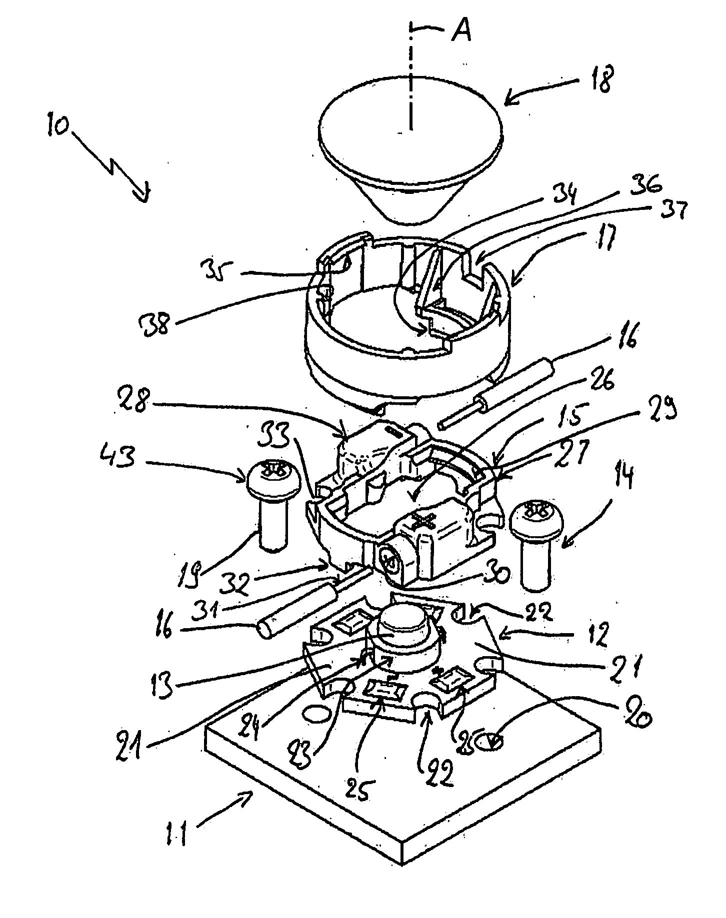
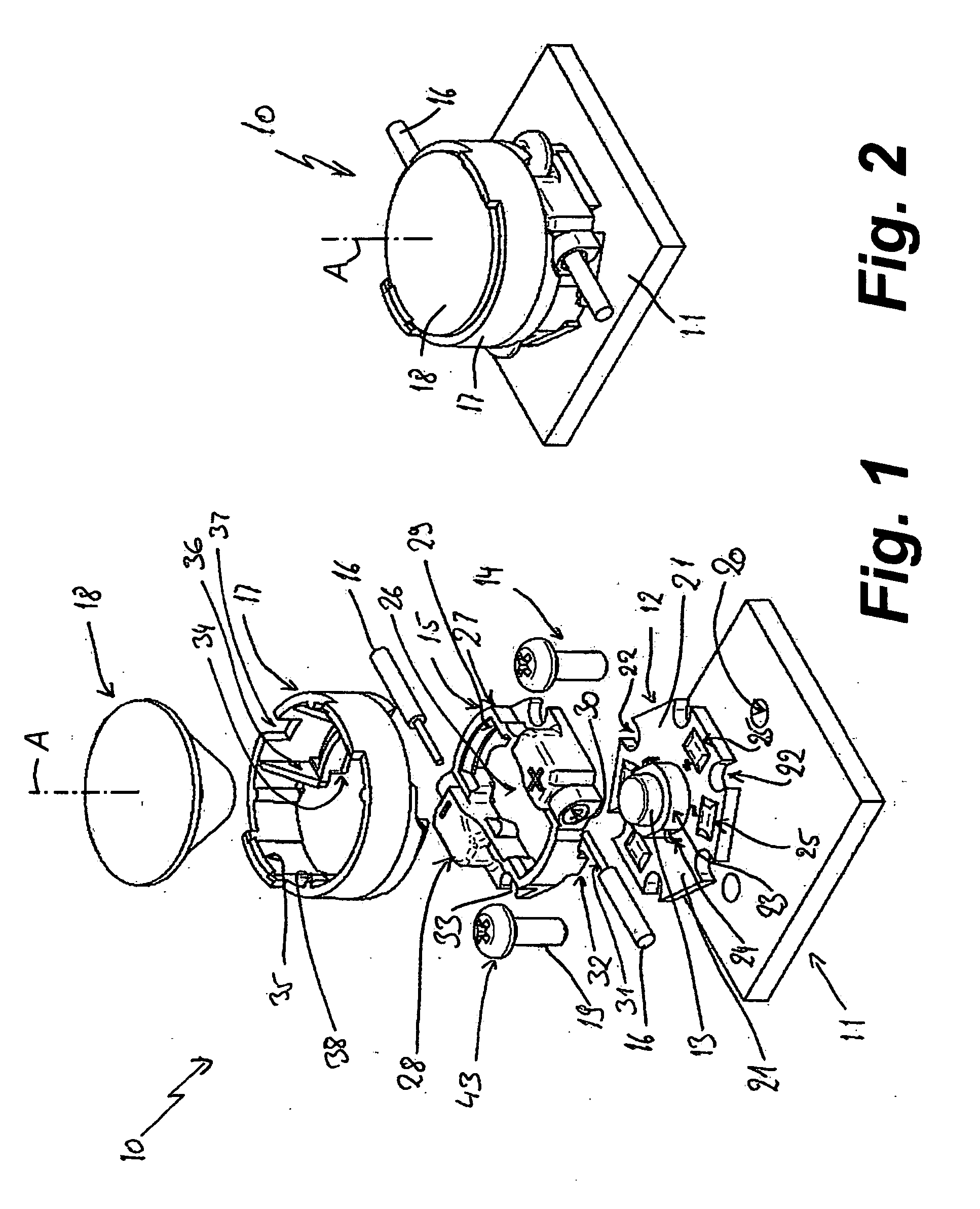
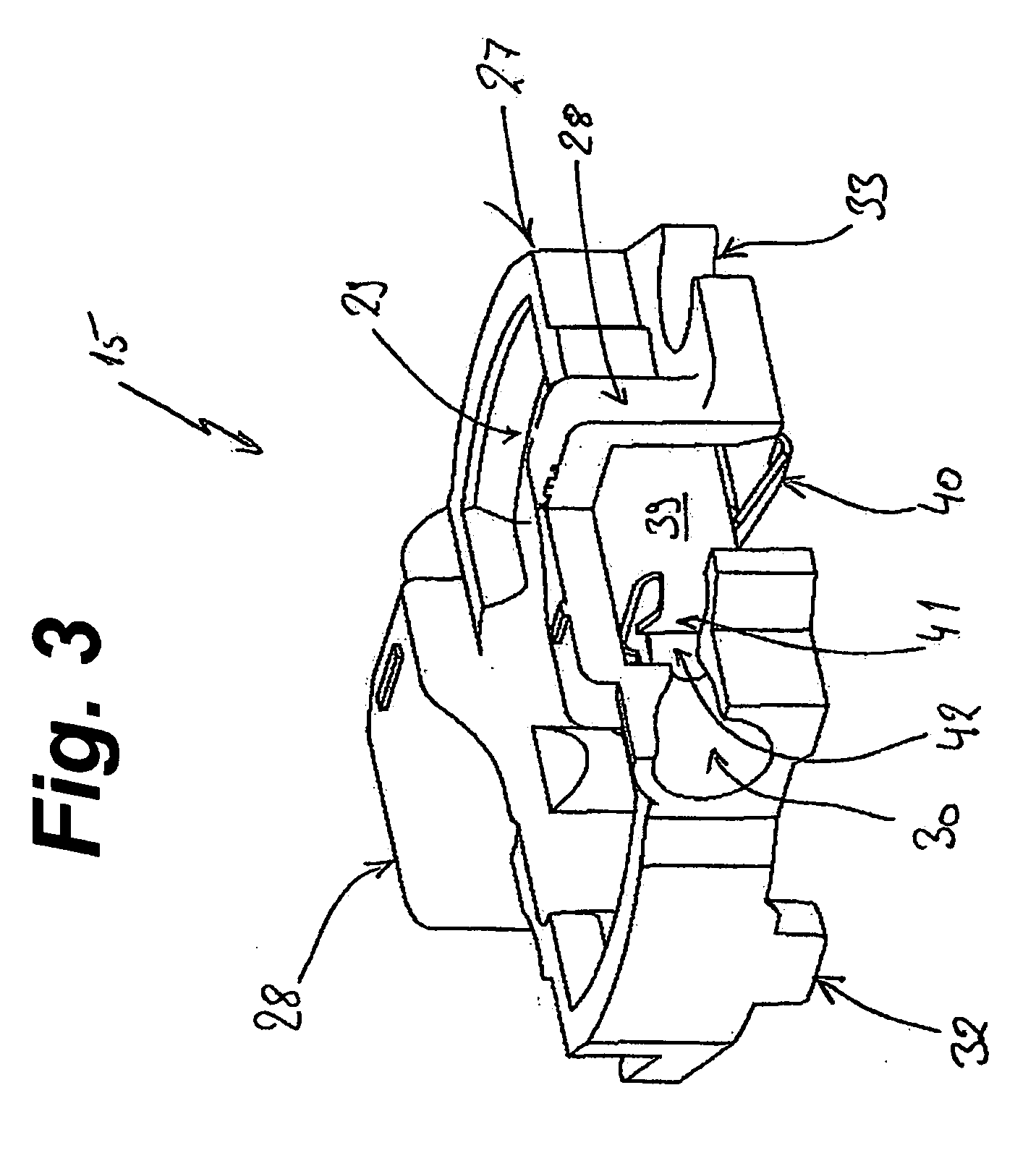
[0029]As seen in FIGS. 1 and 2 an LED light fixture 1 according to the invention has a base 11, a star circuit board 12 carrying an LED 13, a connector 15 that can be mounted on the base 11 by means of screws 14 and that serves for solderless connection of hookup cables 16, a lens holder 17, and a lens 18. The structure is generally centered on an axis A passing centrally through the LED 13 and perpendicular to the plane of the base 11.

[0030]The base 11 has a dual function for the light fixture 10. On the one hand, the light fixture 10 is attached to the base by means of the screws 14; on the other hand, the base serves to dissipate heat generated by the LED 13. The base 11 as well as the star circuit board 12 is made from a material that conducts heat well, usually aluminum. Threaded bores 20 in the base 13 receive the shanks 19 of the attachment screws 14.

[0031]The star circuit board 12 here has six arms 21 separated by radially open cutouts 22 essentially in the shape of a circle...


PUM


Abstract

A printed circuit board having an upper face provided with contact traces and pads with a light-emitting diode fixed to the board and connected to the traces. A connector juxtaposed is with the pads and carries a contact element having a leg bearing with spring force on one of the pads and formations gripping a hookup wire. At least one fastener engages through the connector and circuit board with a heat-sink base and presses the connector against the circuit board and the circuit board against the base.

Description

FIELD OF THE INVENTION[0001]The present invention relates to a connector for a light-emitting diode (LED) mounted on a circuit board. More particularly this invention concerns a light fixture incorporating such an LED.BACKGROUND OF THE INVENTION[0002]LEDs are being used with increasing frequency in the lighting industry as a replacement for conventional light sources, such as electric light bulbs and fluorescent light fixtures, for reduced energy consumption and smaller fixture size. Examples of lighting of this type are step lights, emergency lighting and path lighting to identify emergency exit routes as well as lighting installed in the floor for decorative purposes. Furthermore, the LED is becoming increasingly important as lighting to replace conventional room and building lighting. Lights utilizing LEDs arranged on a printed circuit board are known, for example, from DE 10 2004 004 779 or U.S. Pat. No. 7,182,627.[0003]High-output LEDs, as are increasingly being used, however, ...

Claims


Application Information

Patent Timeline
IPC IPC(8): H01R12/36H01L33/00H01L33/58H01R12/57
CPCH01R4/4818H01R13/2442H01R12/714H01R13/7175H01R13/6215H01R4/48185
Inventor VOGT, KARL-WILHELMTAUBER, DANIELPLIKUN, FREDDI
Owner BJB GMBH & CO KG
Why Eureka
Try Eureka