System and method of fault detection, diagnosis and prevention for complex computing systems

a technology of complex computing and system fault detection, applied in the field of software diagnostics, can solve problems such as software failures, software failures, and difficulty in identifying the source of system failures, and achieve the effects of reducing preventing software failures, and improving the complexity of software systems

Inactive Publication Date: 2009-07-30
IBM CORP
View PDF73 Cites 84 Cited by
  • Summary
  • Abstract
  • Description
  • Claims
  • Application Information

AI Technical Summary

Benefits of technology

[0012]As a result of the summarized invention, technically we have achieved a solution that can be implemented to capture failures that arise in software systems during runtime as a result of complex in...

Problems solved by technology

As the complexity of software systems increases, so too does the difficulty of identifying the source of failures in the system.
Software failures are caused by errors (also known as bugs) that prevent the system from behaving as intended.
Many bugs arise from oversights and errors made during design, coding, and data entry.
Bugs can have a wide variety of effects, with varying levels of inconvenience.
While some bugs may have only a subtle effect on a system's functionality and thus lie undetected for some time, more serious bugs may cause the system or applications running within the system to crash or freeze, leading to a denial of service.
Nevertheless, this level of testing fails to consider any implementation constraints that might exist, such as concurrency, distribution, persistence, how the system is to be built, or how the system is to be implemented in different computing configurations, and, as a result, is generally insufficient to capture integration errors, performance problems, and other system-wide issues that result from the complex interactions between different objects in large, software systems implementing multitasking or other forms of concurrency control, such as operating systems or database systems.
Often, rather than simply arising from individual problems with the...

Method used


Image

  • System and method of fault detection, diagnosis and prevention for complex computing systems
  • System and method of fault detection, diagnosis and prevention for complex computing systems
  • System and method of fault detection, diagnosis and prevention for complex computing systems

Examples


Embodiment Construction

[0018]While the specification concludes with claims defining the features of the invention that are regarded as novel, it is believed that the invention will be better understood from a consideration of the description of exemplary embodiments in conjunction with the drawings. It is of course to be understood that the embodiments described herein are merely exemplary of the invention, which can be embodied in various forms. Therefore, specific structural and functional details disclosed in relation to the exemplary embodiments described herein are not to be interpreted as limiting, but merely as a representative basis for teaching one skilled in the art to variously employ the present invention in virtually any appropriate form. Further, the terms and phrases used herein are not intended to be limiting but rather to provide an understandable description of the invention.

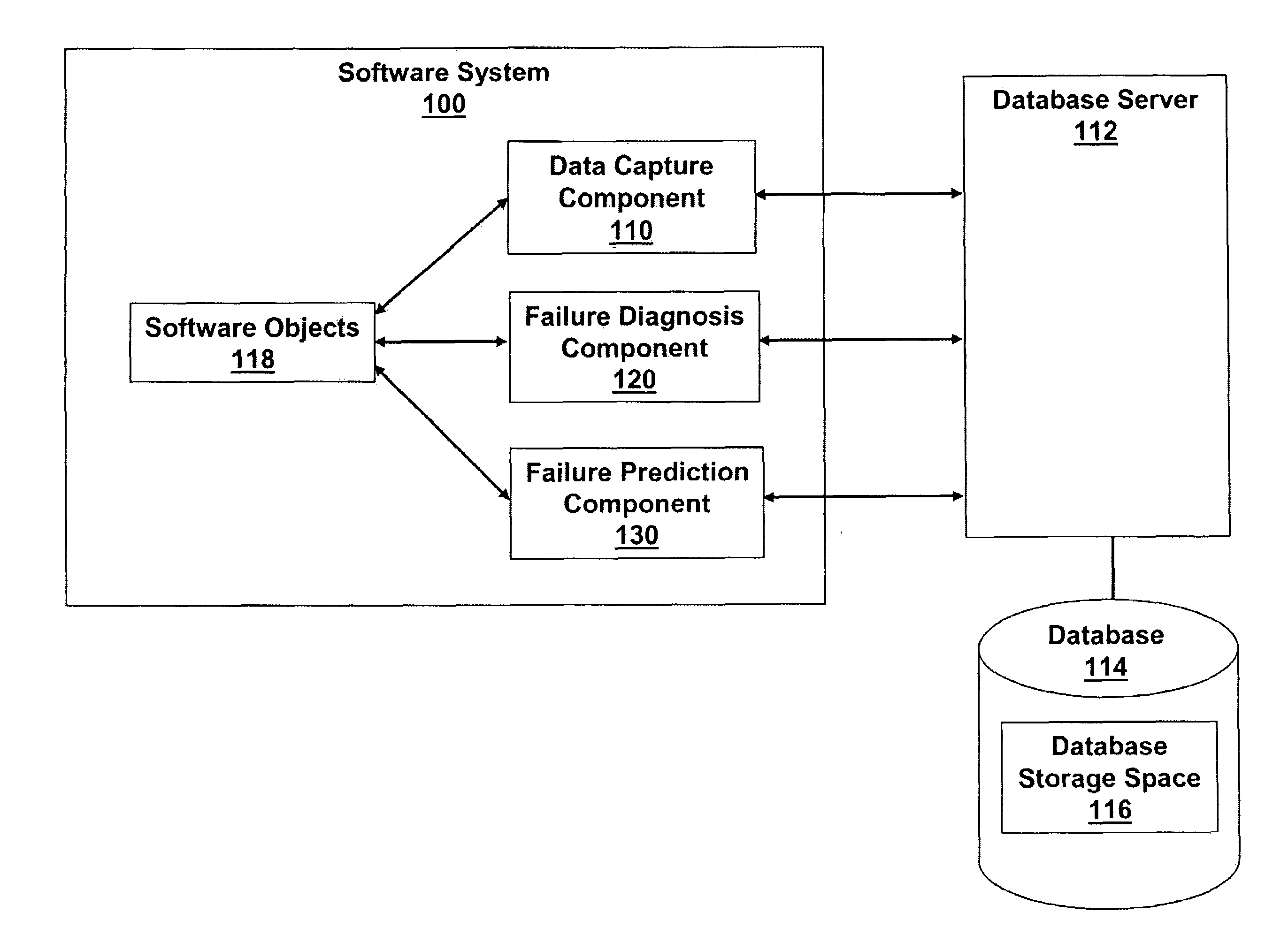
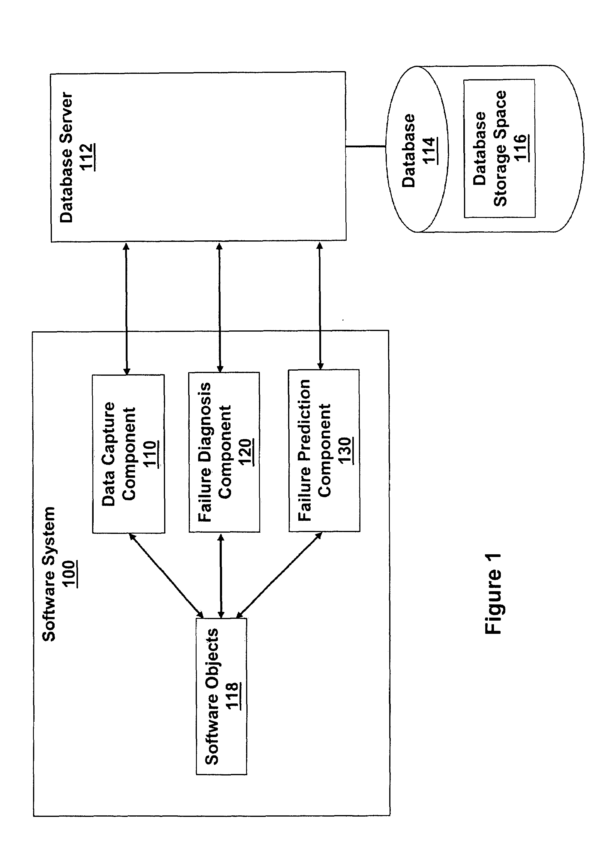
[0019]Exemplary embodiments of the present invention can be implemented to provide a method, system, and apparatus...


PUM


Abstract

A method is provided for diagnosing failures in an object-oriented software system. The method comprises collecting runtime diagnostic information; maintaining a record of the diagnostic information in a storage buffer; and dynamically updating the record of the diagnostic information to include a group of the diagnostic information collected over a most recent occurrence of a predetermined interval. The diagnostic information includes at least one set of call stack information for at least one currently running application and at least one set of other information. Each of the at least one set of other information is selected from a set of memory access information, a set of data access information, and a set of paging information for each currently executing process.

Description

BACKGROUND OF THE INVENTION[0001]1. Field of the Invention[0002]Exemplary embodiments of the present invention relate to software diagnostics, and more particularly, to diagnostics for the interactions between objects in a complex software system.[0003]2. Description of Background[0004]A software system is a system based on software components that form part of a computer system, which is a configuration of functional units (that is, hardware, software, firmware, resources, etc.) according to their nature, number, and chief characteristics. The details of a configuration, including how software systems are implemented therewithin, affects system function and performance. A software component is a system element that offers a predefined service and is able to communicate with other components. Software systems, which can be very large and complex, are typically described in terms of software architectures that specify the software components comprising the systems, the externally vis...

Claims


Application Information

Patent Timeline
IPC IPC(8): G06F11/36
CPCG06F11/0766G06F11/0718
Inventor MUKHERJEE, MAHARAJ
Owner IBM CORP
Why Eureka
Try Eureka