Monolithic printhead with multiple ink feeder channels and relative manufacturing process

a monolithic printhead and feeder channel technology, applied in the field of printing heads, can solve the problems that the patents quoted do not solve the problem described below, and achieve the effect of maximal mechanical robustness of the lamina

Inactive Publication Date: 2007-10-02
TELECOM ITALIA SPA +1
View PDF13 Cites 0 Cited by
  • Summary
  • Abstract
  • Description
  • Claims
  • Application Information

AI Technical Summary

Benefits of technology

[0022]The object of this invention is that of producing a monolithic head in which the width of the lamina is the lowest possible, so that mechanical robustness of the lamina is maximal.
[0023]A further object is that of producing a monolithic head in which the lamina is not subjected to vibrations caused by the sudden formation and successive collapse of the vapour bubble.
[0024]Yet another object is that of rendering the emission frequency of the droplets of ink maximal by producing a time constant τ of the ejector that is as short as possible, while simultaneously satisfying the critical damping condition of the meniscus.
[0027]Yet another object is that of increasing the degrees of freedom of design of the ejector, disposing of the additional parameter that is the number of elementary ducts in parallel.

Problems solved by technology

However the solutions described in the patents quoted do not solve the problem described below.

Method used


Image

  • Monolithic printhead with multiple ink feeder channels and relative manufacturing process
  • Monolithic printhead with multiple ink feeder channels and relative manufacturing process
  • Monolithic printhead with multiple ink feeder channels and relative manufacturing process

Examples


Embodiment Construction

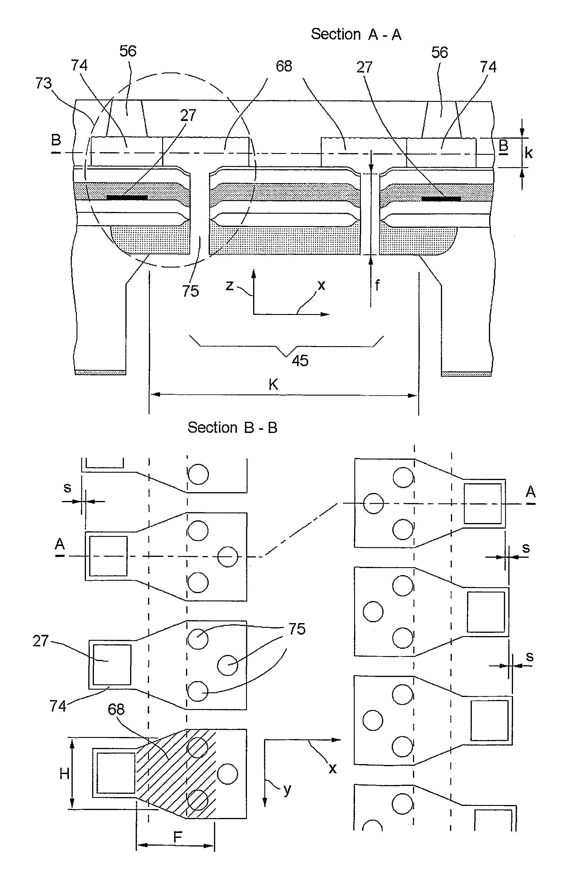
[0048]FIG. 7 represents a section along a plane AA and a section along a plane BB of some ejectors, according to this invention. For simplicity's sake, the other parts of the head are not depicted as they are already known and do not concern the invention. The following are labelled in the figure:[0049]a substrate 140 of Silicon P;[0050]a structural layer 107, according to the invention, of a thickness preferably between 15 and 60 μm and comprising negative photoresists, of the polyamide or epoxy type or of epoxy resin;[0051]a chamber 74 according to the invention, produced in the structural layer 107;[0052]the resistor 27 on the bottom of the chamber 74;[0053]a groove 45 having two parallel walls 126 and width E;[0054]a lamina 67 of width K and thickness p, which has an upper face 170 and a lower face 171;[0055]an N-well layer 36;[0056]a conducting layer 26 made, as a non-restrictive example, from a layer of Tantalum of thickness preferably between 0.4 and 0.6 μm, covered by a laye...


PUM


Abstract

A thermal ink jet printhead (40) for the emission of drops of ink on a print medium (46) comprises a tank (103) containing ink (142), a lamina (67), a groove (45) and a plurality of ejectors (73), each of which comprises in turn a chamber (74) placed laterally with respect to the groove (45), and fluidly connected thereto by means of a plurality of elementary ducts (75) produced on said lamina (67).

Description

[0001]This is a U.S. National Phase Application Under 35 USC 371 and applicants herewith claim the benefit of priority of PCT / ITO1 / 00170 filed Apr. 3, 2001, which was published Under PCT Article 21(2) in English and Application No. T02000A000335 filed in Italy on Apr. 10, 2000.TECHNICAL FIELD[0002]This invention relates to a printhead used in equipment for forming, through successive scanning operations, black and colour images on a print medium, usually though not exclusively a sheet of paper, by means of the thermal type ink jet technology, and in particular to the head actuating assembly, and the relative manufacturing process.BACKGROUND ART[0003]Depicted in FIG. 1 is an ink jet colour printer on which the main parts are labelled as follows: a fixed structure 41, a scanning carriage 42, an encoder 44 and printheads 40 which may be either monochromatic or colour, and variable in number.[0004]The printer may be a stand-alone product, or be part of a photocopier, of a plotter, of a ...

Claims


Application Information

Patent Timeline
Patent Type & Authority Patents(United States)
IPC IPC(8): B41J2/05B41J2/14B41J2/16
CPCB41J2/1404B41J2/14145B41J2/1603B41J2/1628B41J2/1631B41J2/1635B41J2/1639B41J2/1645B41J2/1629B41J2002/14467
Inventor CONTA, RENATOSCARDOVI, ALESSANDRO
Owner TELECOM ITALIA SPA
Why Eureka
Try Eureka