Method Of Optical Data Storage

a data storage and optical readonly technology, applied in the field of optical data storage and optical readonly memory, can solve the problems of difficult installation of fibre networks and manual routing changes, unsatisfactory markings such as bar codes on fibres, and inconvenient use of data storage devices

Inactive Publication Date: 2007-11-29
REDFERN OPTICAL COMPONENTS
View PDF6 Cites 2 Cited by
  • Summary
  • Abstract
  • Description
  • Claims
  • Application Information

AI Technical Summary

Benefits of technology

[0009] The multi-channel grating typically has a grating structure that may be created by superposition a plurality of second, typically simpler, grating structures. Because of the superposition, the gratings can be relatively short and it is possible to store a relatively large amount of encoded information in a relatively short grating. As the encoded information is stored in the waveguide, such as in a core of a waveguide, mechanical robustness typically is larger than that of conventional data storage devices such as CD drives drives. The encoded information is retrievable from the optical radiation that passed through the multi-channel waveguide and retrieval of the encoded information, for example using a suitable optical analyser, typically only requires a minimum of mechanical components. Further, the optical information may be stored (and retrieved) in a manner that is not affected by water.

Problems solved by technology

Installation of fibre networks and manual routing changes therefore are difficult tasks and mistakes can be made.
The optical fibres are typically marked so that they can be identified, but suitable markings such as bar codes on the fibres are not ideal as they can only be identified locally.
However, such data storage devices typically are mechanically complex and sensitive devices.
For example, CD drives are often sensitive to mechanical impact and the CD's themselves are often easily damaged by scratching their surfaces.

Method used


Image

  • Method Of Optical Data Storage
  • Method Of Optical Data Storage
  • Method Of Optical Data Storage

Examples


Embodiment Construction

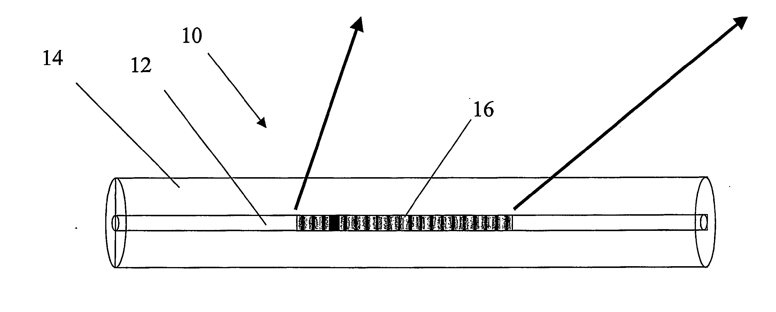
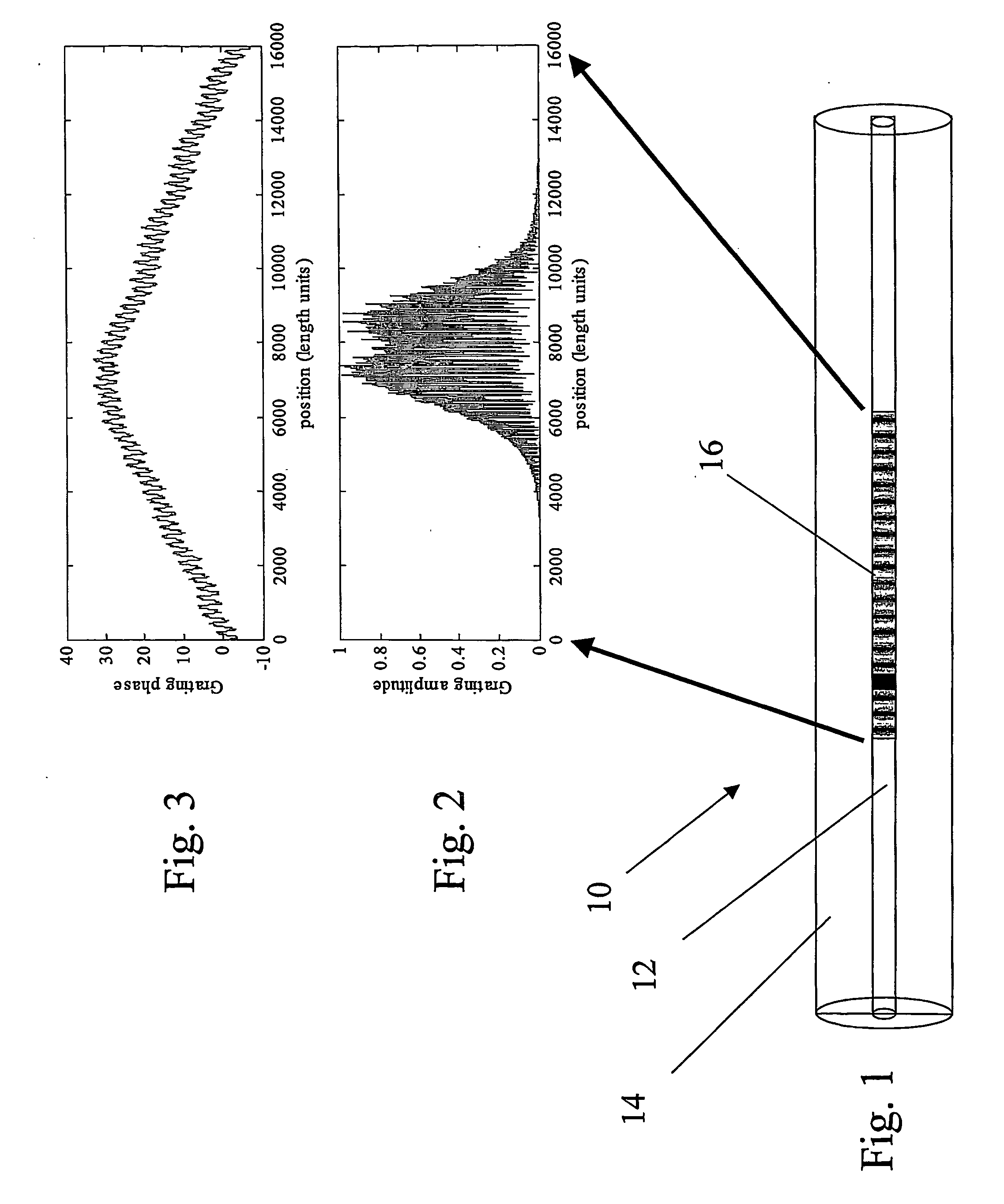
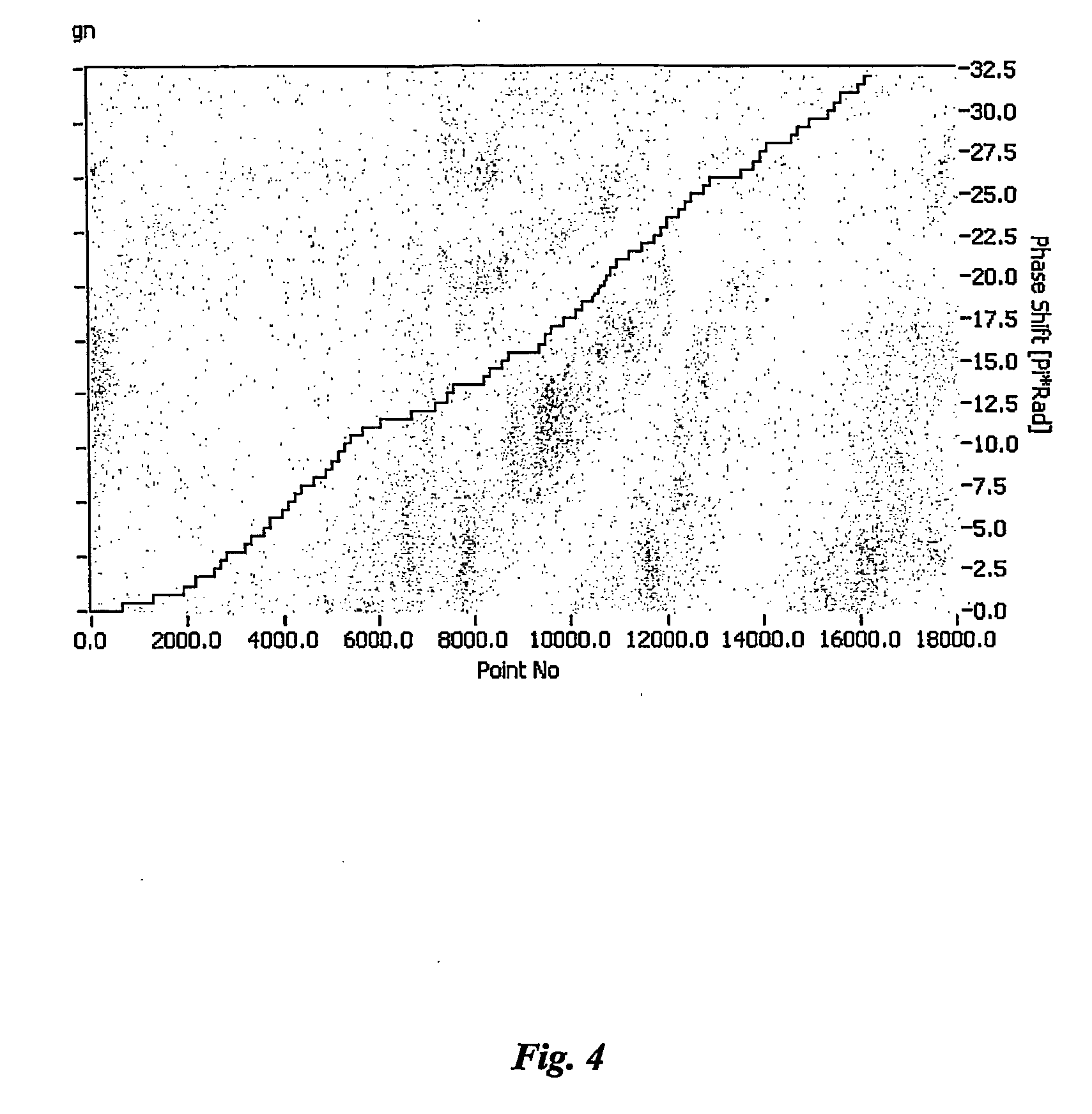
[0040] Referring to FIG. 1, an optical storage device according to an embodiment of the present invention is now described. In this embodiment the optical storage device is provided in form of an optical fibre 10. The optical fibre 10 has a core 12 and a cladding 14. Written into the core 12 is a refractive index variation that forms a multi-channel Bragg grating 16. FIGS. 2 and 3 show the amplitude and phase versus position plots for the grating 16 which correspond to encoded information. Light of suitable wavelength that is directed through the Bragg grating 16 will experience changes in amplitude and phase that are characteristic for the encoded information and the light can be processed to retrieve the encoded information.

[0041] In this embodiment, the Bragg grating 16 has a profiled envelope. Varying an amplitude of the envelope of the refractive index profile has a direct analogy to AM radio where audio information is impressed on the envelope of an RF carrier tone. However i...


PUM


Abstract

The present invention provides a method of storing data in an optical data storage device. The method comprises the step of encoding information and determining a multi-channel grating structure for the encoded information. The method further comprises the step of applying the grating structure to an optical waveguide in a manner such that in use the multi-channel grating will effect a change of a property of optical radiation that passes through the waveguide. The change of the property is characteristic for the encoded information. The present invention further provides an optical read only memory having a multi-channel grating.

Description

FIELD OF THE INVENTION [0001] The present invention broadly relates to a method of optical data storage and to an optical read-only memory. BACKGROUND OF THE INVENTION [0002] The amount of optical fibre that is being installed is constantly increasing. Metropolitan areas already have dense networks of optical fibres. For example, in exchange stations often hundreds of fibres are branching and crossing. Installation of fibre networks and manual routing changes therefore are difficult tasks and mistakes can be made. The optical fibres are typically marked so that they can be identified, but suitable markings such as bar codes on the fibres are not ideal as they can only be identified locally. Optical fibres often have a length of many (hundreds) kilometres and a large number of bar codes needs to be applied to the fibres in intervals to ensure that the optical fibre can be identified at any interrogation position. [0003] There is a need for a better method of coding fibres and thereby...

Claims


Application Information

Patent Timeline
Patent Type & Authority Applications(United States)
IPC IPC(8): G02B6/10G02B6/02G02B6/255G11C13/04
CPCG02B6/02085G11C13/04G02B6/255G02B6/02
Inventor ENGLUND, MARK ANDREWEDVELL, LARS GORANGRAF, ANDREW
Owner REDFERN OPTICAL COMPONENTS
Why Eureka
Try Eureka