
Pipe compensation system

Inactive Publication Date: 2009-08-06
METRAFLEX
View PDF13 Cites 25 Cited by
  • Summary
  • Abstract
  • Description
  • Claims
  • Application Information

AI Technical Summary

Benefits of technology

[0005]The loop member includes a first and second connector end each configured to mate with one of the open ends of the divided pipe, and a length of tubing extending between the first and second connector ends having at least one bend therein causing the tubing to extend away from the longitudinal axis of the pipe, the tubing being sufficiently flexible so as to accommodate a movement between the open ends of the pipe both axially and laterally, sufficient to relieve stress in the pipeline. In some installations this could be as little as ⅛th of an inch, while in other installations it may be greater than a diameter of the pipe.

Problems solved by technology

In conventional plumbing installations, there is the inevitable problem of movement of pipes in the installation.
Such movement often causes the pipes to leak or break apart.

Method used


Image

  • Pipe compensation system
  • Pipe compensation system
  • Pipe compensation system

Examples


first embodiment

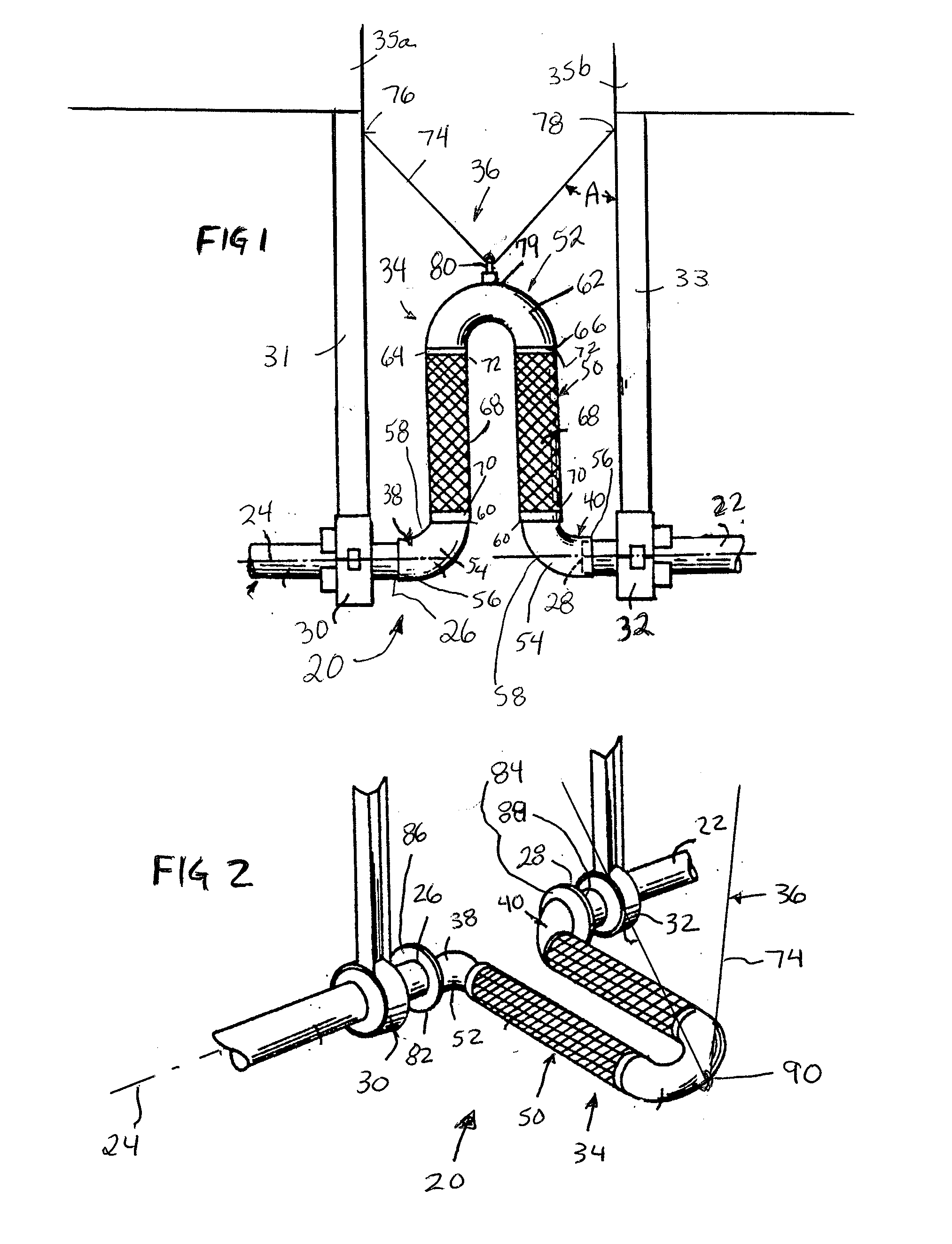
[0012]In FIG. 1 a compensation system 20 is illustrated for use with a pipe 22 extending along a longitudinal axis 24 and divided along its length to form a pair of open ends 26, 28. The open ends 26, 28 may be arranged at any position along a length of pipe, including at a corner junction, or at a point where the pipe 22 protrudes from an opening in a wall. The compensation system 20 may also be connected directly to another component of a pipeline, such as a pump, elbow, wye, or other component normally associated with pipelines. The pipe 22 may be part of a pipeline within a single building or structure, or may extend between two or more structures. The pipe 22 is supported at first 30 and second 32 spaced apart points, which points are subject to movement relative to one another. The first and second points 30, 32 may include pipe guides or pipe hangers 31, 33 which are secured to structures 35a, 35b. The structures 35a, 35b may be part of a single structure or building, or may ...

second embodiment

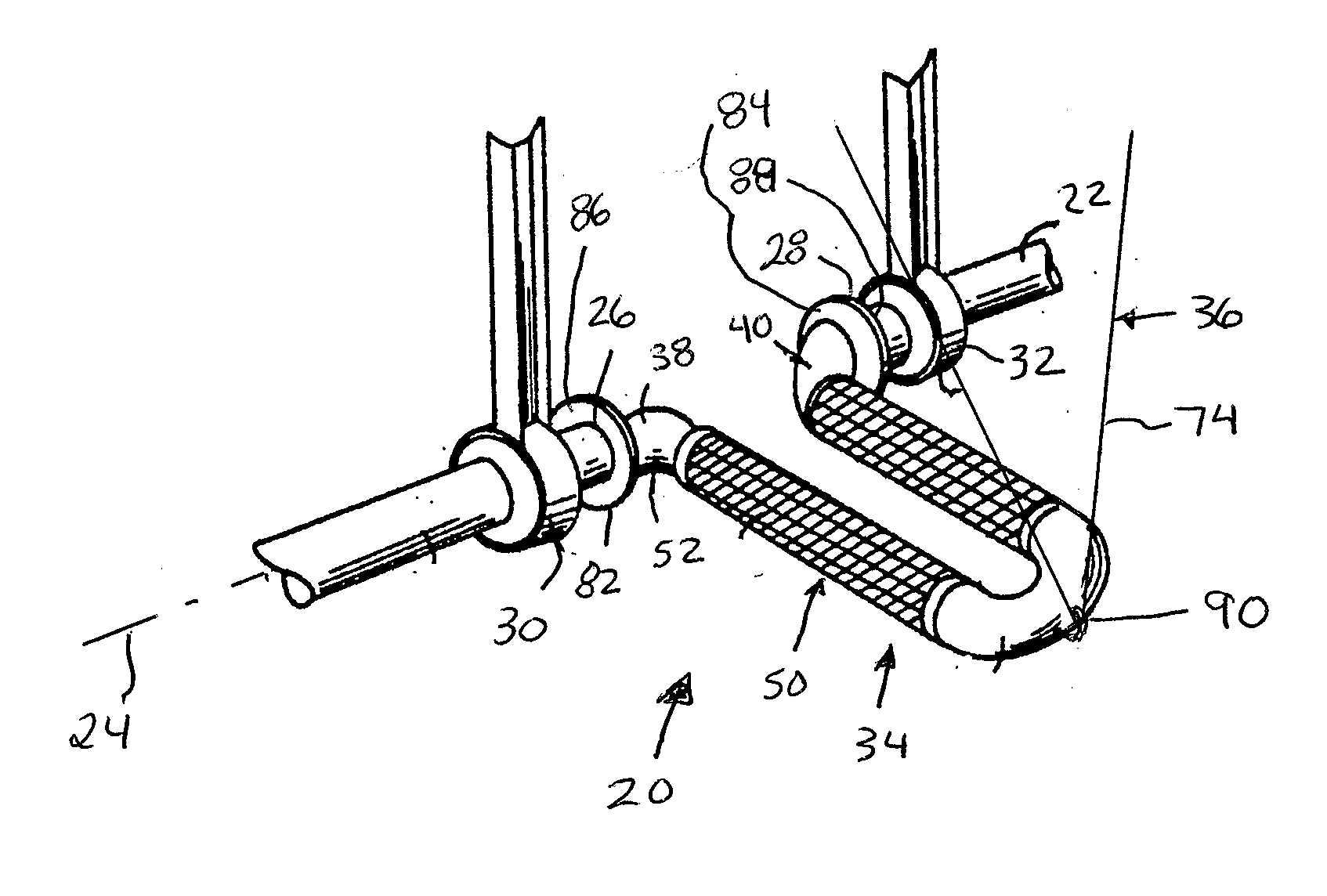
[0020]In FIG. 2 the compensation system 20 is illustrated for use with the pipe 22. Again, the pipe 22 is supported at the first 30 and second 32 spaced apart points, which points are subject to movement relative to one another.

[0021]The system 20 includes the loop member 34 attached to the pipe 22 at the open ends 26, 28 and the support system 36 for the loop member 34.

[0022]The loop member 34 includes the first 38 and second 40 connector ends each configured to mate with one of the open ends 26, 28 of the divided pipe 22. In this embodiment, the connector ends 38, 40 are provided with flanges 82, 84 which mate with flanges 86, 88 at the open ends 26, 28 of the pipe 22. The length of tubing 50 extends between the first and second connector ends 38, 40. The tubing 50 has at least one bend 52 therein causing the tubing to extend away from the longitudinal axis 24 of the pipe 22. In the embodiment shown in FIG. 2, the loop member 34 extends horizontally away from the pipe axis 24. The...

third embodiment

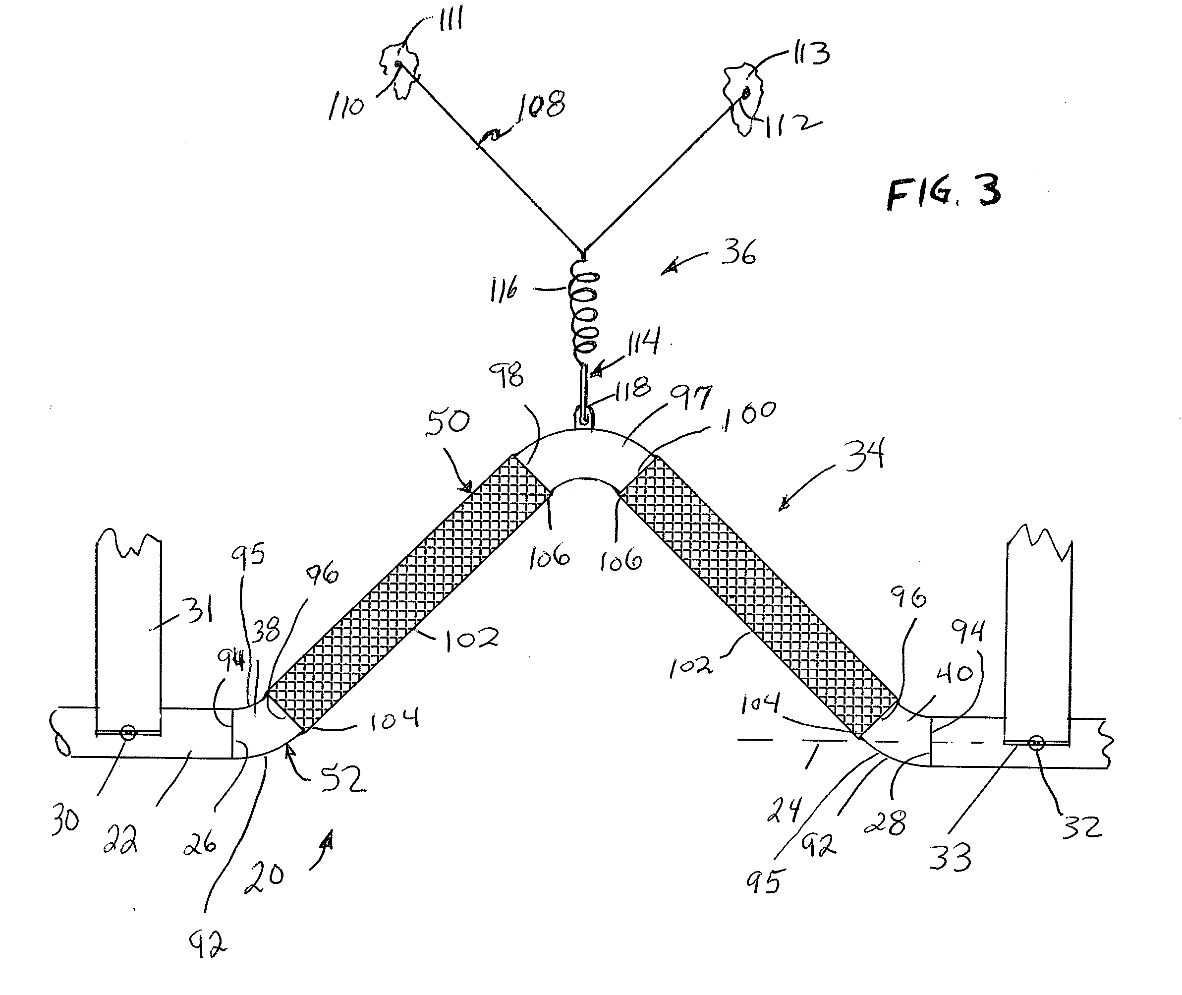
[0025]In FIG. 3 the compensation system 20 is illustrated for use with the pipe 22 extending along the longitudinal axis 24 and divided along its length to form the pair of open ends 26, 28. The pipe 22 is supported at the first 30 and second 32 spaced apart points, which points are subject to movement relative to one another. The first and second points 30, 32 may comprise pipe hangers 31, 33 which are secured to structures (not shown). The two points 30, 32 may be located on opposite sides of a separation from one another, and therefore may be subject to movement relative to one another.

[0026]The system 20 includes the loop member 34 attached to the pipe 22 at the open ends 26, 28 and the support system 36 for the loop member 34.

[0027]The loop member 34 includes the first 38 and second 40 connector ends each configured to mate with one of the open ends 26, 28 of the divided pipe 22. The length of tubing 50 extends between the first and second connector ends 38, 40. The tubing 50 h...


PUM


Abstract

A compensation system for use with a divided pipe having a pair of open ends and being supported at first and second spaced apart points which are moveable relative to one another. A loop member attaches to the open ends of the pipe and is supported by a support system. The loop member includes a bend causing the loop member to extend away from the pipe, the loop member being flexible enough to accommodate a movement between the open ends of the pipe. The support system includes a flexible support having a first end secured to move with the first point and a second end secured move with the second point. Also, a support connection is provided at the loop member for engagement by the flexible support between the two ends to permit movement of the loop member relative to the pipe, the support connection permitting movement of the flexible support relative to the tubing.

Description

BACKGROUND OF THE INVENTION[0001]The present invention relates to devices for absorbing movement in runs or lines of pipe.[0002]In conventional plumbing installations, there is the inevitable problem of movement of pipes in the installation. Movement of the pipes may be caused by expansion, contraction, building movement, earthquake, explosion, or other factors. Such movement often causes the pipes to leak or break apart.[0003]Flexible pipe loops have been employed to compensate for and absorb pipe movements. For example, U.S. Pat. No. 5,195,784 to Richter, U.S. Pat. No. 5,803,506 to Argersinger and U.S. Pat. No. 7,195,284 to Garton, et al. disclose such flexible pipe loops.SUMMARY OF THE INVENTION[0004]A compensation system is provided for use with a pipe extending along a longitudinal axis and divided along its length to form a pair of open ends. The pipe is supported at first and second spaced apart points, which points are subject to movement relative to one another. The system ...

Claims


Application Information

Patent Timeline
IPC IPC(8): F16L51/00F16L3/00
CPCF16L51/04F16L3/015
Inventor BOCHENEK, ZBIGNIEWPLATUSICH, BRUCE M.RICHTER, JAMES R.CLAUSS, JAMES DAVID
Owner METRAFLEX
Features
  • Generate Ideas
  • Intellectual Property
  • Life Sciences
  • Materials
  • Tech Scout
  • Unparalleled Data Quality
  • Higher Quality Content
  • 60% Fewer Hallucinations
Learn More