Pickup-style work vehicle
- Summary
- Abstract
- Description
- Claims
- Application Information
AI Technical Summary
Benefits of technology
Problems solved by technology
Method used
Image
Examples
second embodiment
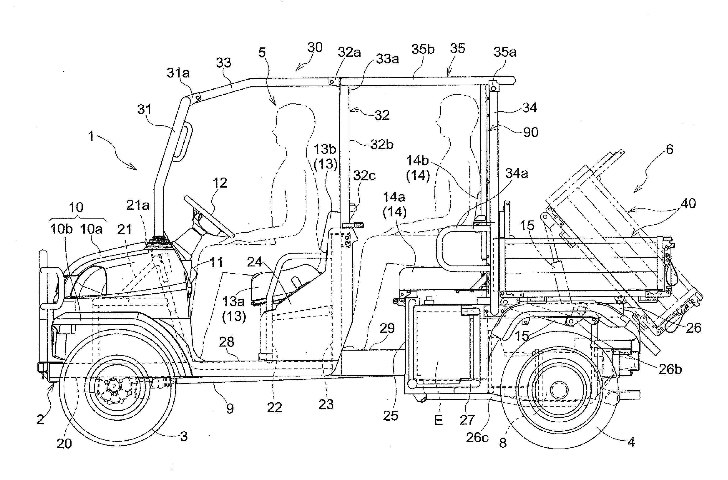
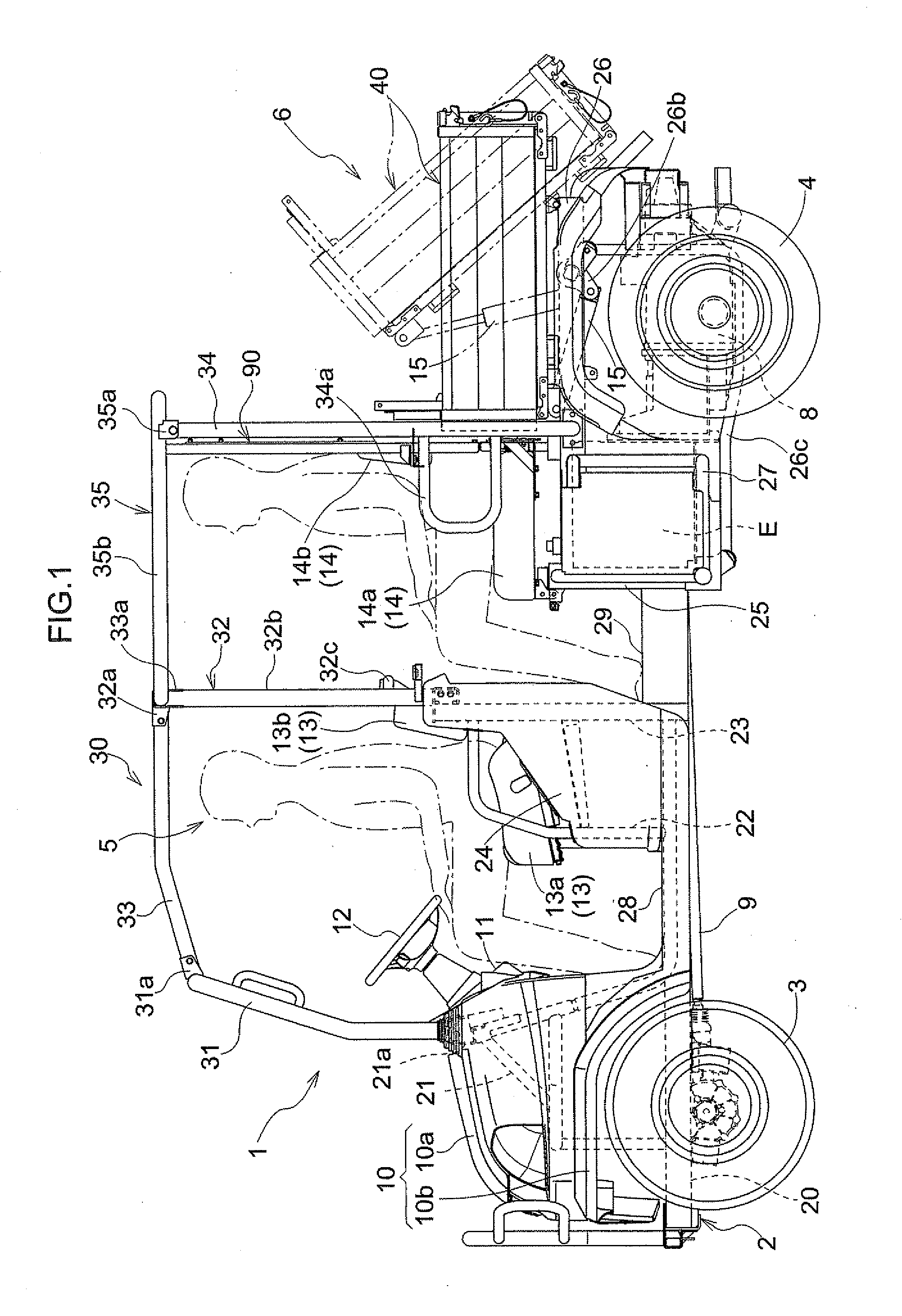
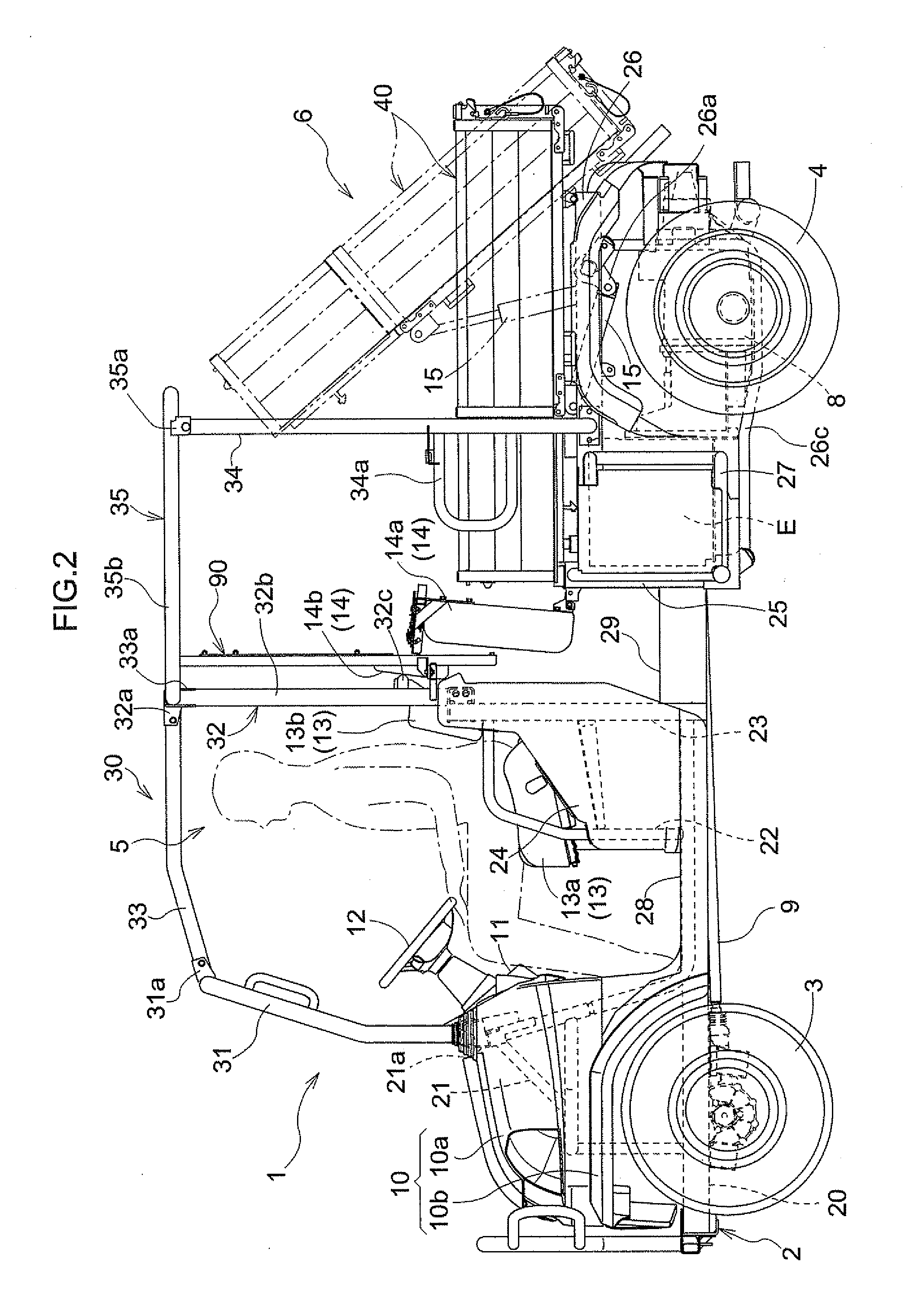
[0143]In the first embodiment described above, the loading floor size changeover mechanism was shown and described in which the right and left forward side wall portions 45 were folded rearwardly after raising and folding the front bottom portion 42 with the front wall portion 46 rearwardly to the upright position. Different order for folding the front wall portion 46, the front bottom portion 42, and the right and left forward side wall portions 45 can be adapted. For example, the loading-platform size changeover mechanism may be configured such that the front bottom portion 42 with the front wall portion 46 are raised rearwardly to the upright position folded after folding the right and left forward side wall portions 45 rearwardly.
[0144]While in the first embodiment described above, the loading-platform size changeover mechanism was shown and described in which the loading floor 40 was switched between the extended state and the shortened state by folding the front wall portion 4...
third embodiment
[0148]The first and second embodiments employ the partition member position change mechanism for changing the position of the partition member 90 between the forward position and the rearward position by allowing the partition member 90 to slide along the rail members 96. Instead, a partition member position change mechanism for moving the partition member 90 between the forward position and the rearward position may be employed. More particularly, the partition member position mechanism may allow the partition member 90 to be detachable in which the partition member 90 is removably attached to the ROPS 30 at the forward position or the rearward position, for example. The partition member 90 fixed to the ROPS either one of the forward position and the rearward position is removed, and the removed partition member is fixed to the ROPS 30 at the other of the forward position and the rearward position.
fourth embodiment
[0149]The foregoing first, second and third embodiments employ the partition member position change mechanism for fixing the partition member 90 to the ROPS 30 at the forward position or the rearward position. Instead, a partition member position change mechanism for allowing the partition member 90 to be fixed to the vehicle body at the forward position or the rearward position. For example, the partition member 90 is fixed to the vehicle body frame 2, the front seat support panel 24, the rear deck board 29 or the like at the forward position or the rearward position. The partition member 90 is fixed to a further frame member (not shown) provided separately from the ROPS 30 to extend from the vehicle body frame 2, the front seat support panel 24, the rear deck board 29 or the like. Also, the partition member 90 may be fixed to the ROPS 30 at either one of the forward position and the rearward position while may be fixed to the vehicle body frame 2, the front seat support panel 24, ...
PUM
 Abstract
Description
Claims
Application Information
 - R&D
- Intellectual Property
- Life Sciences
- Materials
- Tech Scout
- Unparalleled Data Quality
- Higher Quality Content
- 60% Fewer Hallucinations
Browse by: Latest US Patents, China's latest patents, Technical Efficacy Thesaurus, Application Domain, Technology Topic, Popular Technical Reports.
© 2025 PatSnap. All rights reserved.Legal|Privacy policy|Modern Slavery Act Transparency Statement|Sitemap|About US| Contact US: help@patsnap.com


