Pickup-style work vehicle

a work vehicle and pick-up technology, applied in the field of pick-up-style work vehicles, can solve the problems of restricting the height of the loading floor at the dumping position, hammering the partition member from covering the rear side of the driver's section, and reducing the efficiency of the dumping operation of the loading floor

Active Publication Date: 2009-09-01
KUBOTA CORP
View PDF2 Cites 37 Cited by
  • Summary
  • Abstract
  • Description
  • Claims
  • Application Information

AI Technical Summary

Benefits of technology

[0005]An object of the present invention is to provide a pickup-style work vehicle that has a partition member capable of covering the rear side of a driver's section when a loading floor is moved to a dumping position, which can prevent the height of the loading floor at the dumping position from being restricted by the partition member.
[0007]With this construction, the partition member placed at the forward position or the rearward position is fixed to the fixing member provided in the vehicle. Thus, when the loading floor is moved to the dumping position, the partition member remains fixed to the fixing member of the vehicle body and is not moved. Only the loading floor is moved to the dumping position in the first or second state. This allows the partition member to cover the rear side of the driver's section even when the loading floor is moved to the dumping position. Also, the partition member is not raised together with the loading floor when the loading floor is moved to the dumping position, which can prevent the height of the loading floor at the dumping position from being restricted by the partition member. As result, the rear side of the driver's section is not opened even when the loading floor is moved to the dumping position, but can be covered by the partition member when the loading floor is moved to the dumping position. In addition, the loading floor can be moved to the dumping position without worrying about the partition member, which can improve efficiency of the dumping operation of the loading floor.
[0009]With this construction, the partition member can be moved along the ROPS smoothly and naturally from the forward position or the rearward position to the rearward position or the forward position by allowing the partition member to slide in the fore-and-aft direction relative to the ROPS to easily change the position of the partition member. On the other hand, the partition member can be stably fixed to the ROPS at the forward position or the rearward position by fixing the partition member slid to the forward position or the rearward position to the ROPS. As a result, the partition member can be rigidly fixed to the ROPS at the forward position or the rearward position, preventing clattering of the partition member that may be caused when the work vehicle is running or the like.

Problems solved by technology

This hampers the partition member from covering the rear side of the driver's section as the loading floor is moved to the dumping position.
Further, when the partition member is moved upward together with the loading floor, the overall height of the work vehicle becomes greater than the partition member as the loading floor is moved to the dumping position, which restricts the height of the loading floor at the dumping position.
Thus, the operator needs to move the loading floor to its dumping position while worrying about the presence of the partition member.
Therefore, there exists a problem that the dumping operation of the loading floor has to be performed carefully, reducing efficiency of the dumping operation of the loading floor.

Method used


Image

  • Pickup-style work vehicle
  • Pickup-style work vehicle
  • Pickup-style work vehicle

Examples


second embodiment

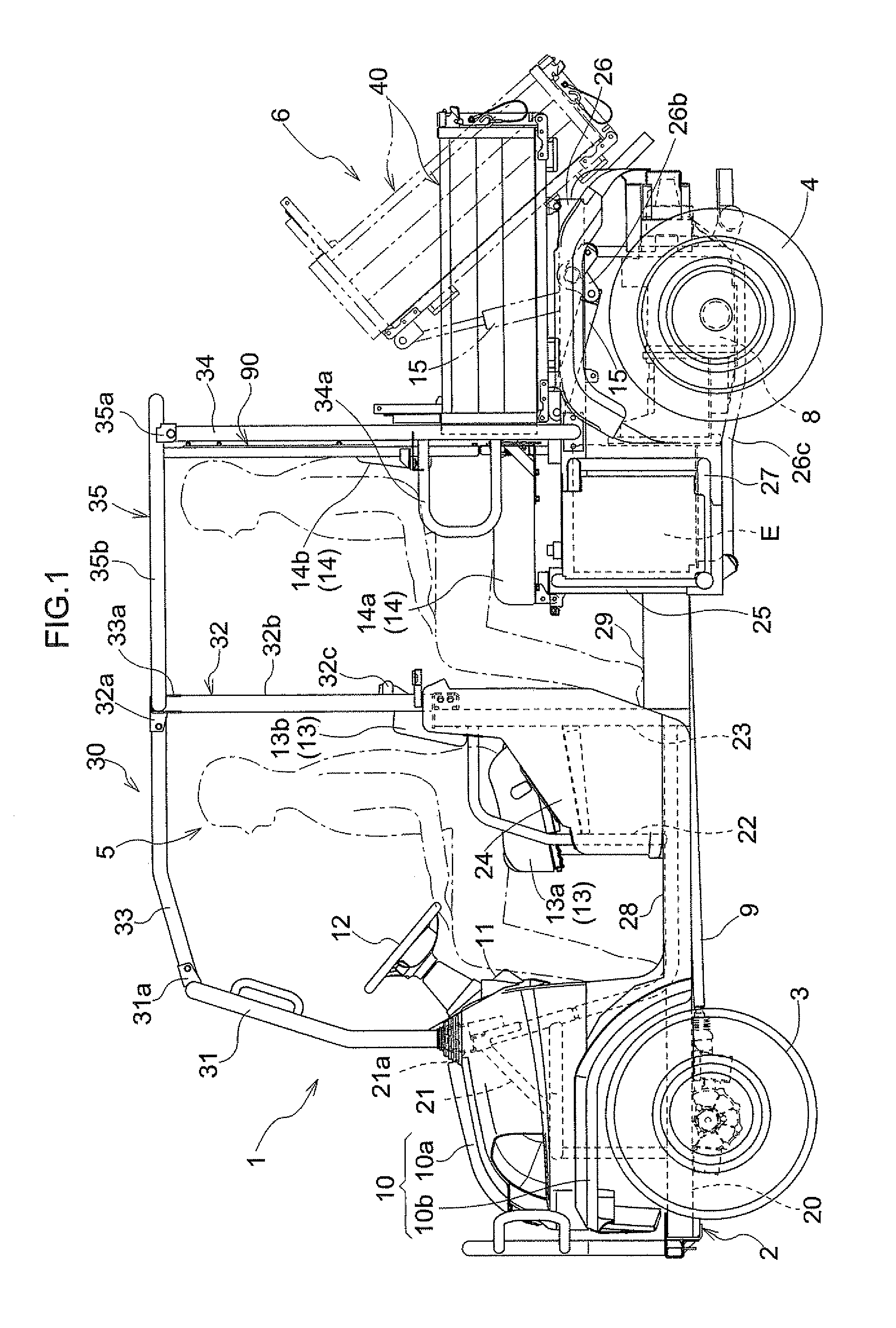
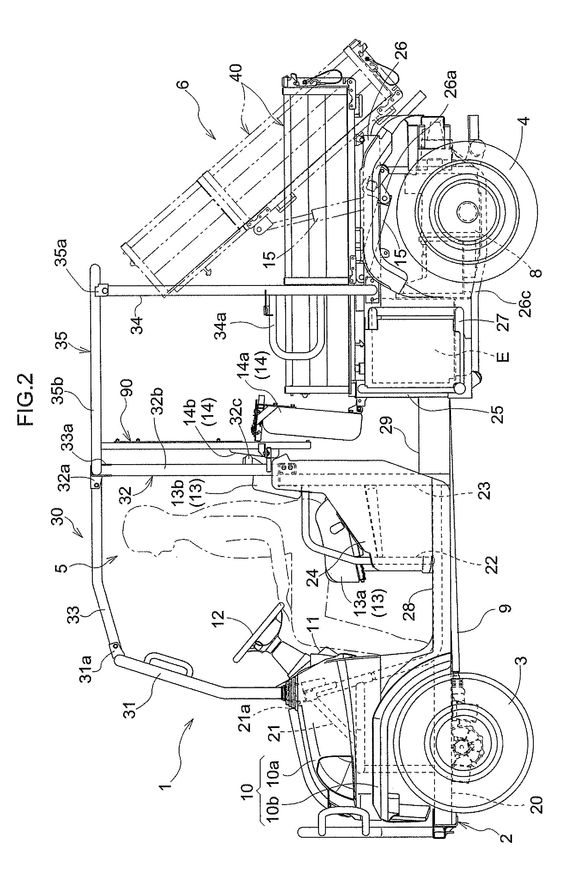
[0143]In the first embodiment described above, the loading floor size changeover mechanism was shown and described in which the right and left forward side wall portions 45 were folded rearwardly after raising and folding the front bottom portion 42 with the front wall portion 46 rearwardly to the upright position. Different order for folding the front wall portion 46, the front bottom portion 42, and the right and left forward side wall portions 45 can be adapted. For example, the loading-platform size changeover mechanism may be configured such that the front bottom portion 42 with the front wall portion 46 are raised rearwardly to the upright position folded after folding the right and left forward side wall portions 45 rearwardly.

[0144]While in the first embodiment described above, the loading-platform size changeover mechanism was shown and described in which the loading floor 40 was switched between the extended state and the shortened state by folding the front wall portion 4...

third embodiment

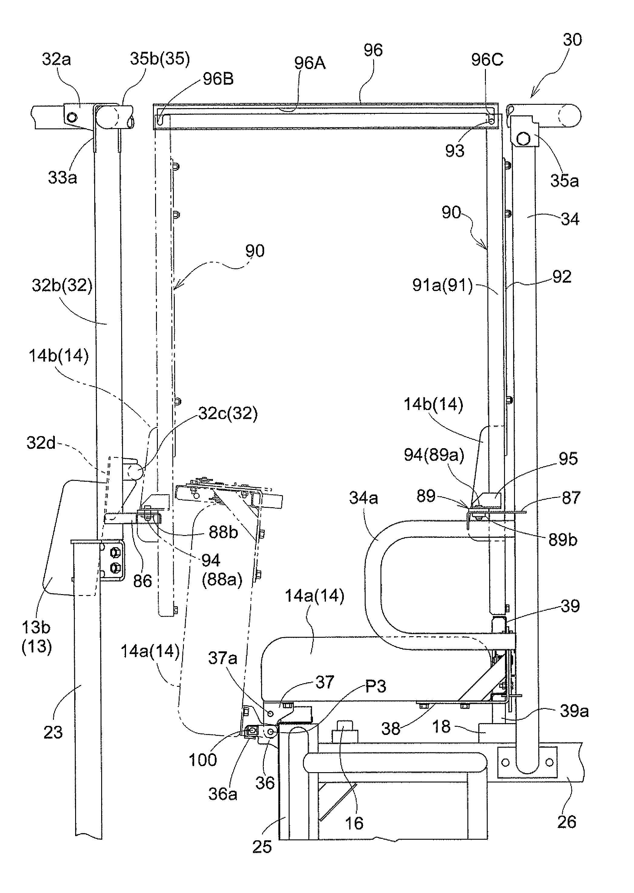
[0148]The first and second embodiments employ the partition member position change mechanism for changing the position of the partition member 90 between the forward position and the rearward position by allowing the partition member 90 to slide along the rail members 96. Instead, a partition member position change mechanism for moving the partition member 90 between the forward position and the rearward position may be employed. More particularly, the partition member position mechanism may allow the partition member 90 to be detachable in which the partition member 90 is removably attached to the ROPS 30 at the forward position or the rearward position, for example. The partition member 90 fixed to the ROPS either one of the forward position and the rearward position is removed, and the removed partition member is fixed to the ROPS 30 at the other of the forward position and the rearward position.

fourth embodiment

[0149]The foregoing first, second and third embodiments employ the partition member position change mechanism for fixing the partition member 90 to the ROPS 30 at the forward position or the rearward position. Instead, a partition member position change mechanism for allowing the partition member 90 to be fixed to the vehicle body at the forward position or the rearward position. For example, the partition member 90 is fixed to the vehicle body frame 2, the front seat support panel 24, the rear deck board 29 or the like at the forward position or the rearward position. The partition member 90 is fixed to a further frame member (not shown) provided separately from the ROPS 30 to extend from the vehicle body frame 2, the front seat support panel 24, the rear deck board 29 or the like. Also, the partition member 90 may be fixed to the ROPS 30 at either one of the forward position and the rearward position while may be fixed to the vehicle body frame 2, the front seat support panel 24, ...


PUM


Abstract

A pickup-style work vehicle comprises a driver's section, a loading floor that is located rearwardly of the driver's section and that can be moved to a dumping position, a loading floor size changeover mechanism that changes a size of the loading floor between a first state in which a front wall portion and a front bottom portion of the loading floor are moved forwardly in a fore-and-aft direction of a vehicle and a second state in which the front wall portion and the front bottom portion of the loading floor are moved rearwardly in the fore-and-aft direction, a fixing member connected to the vehicle, and partition member position change mechanism for changing the position of the partition member in the fore-and-aft direction of the vehicle between a forward position and a rearward position. The partition member when placed at the forward position is located immediately forwardly of the loading floor in the first state while the partition member when placed at the rearward position is located immediately forwardly of the loading floor in the second state.

Description

BACKGROUND OF THE INVENTION[0001]1. Field of the Invention[0002]The present invention relates to a pickup-style work vehicle having a driver's section, and a loading floor that is arranged rearwardly of the driver's section and that can be moved to a dumping position.[0003]2. Description of the Related Art[0004]A conventional pickup-style work vehicle is known from U.S. Pat. No. 6,905,159 (see FIG. 2, FIGS. 5-7), which has a loading floor (shown at 2 in FIG. 2) that is arranged rearwardly of the vehicle and that can be moved a dumping position, and a partition member (shown at 5 in FIG. 1) that is adapted to partition between the loading floor and the driver's section. In this pickup-style work vehicle, as shown in FIG. 6 and FIG. 7 of the above-noted U.S. patent, the partition member can be fixed to the loading floor. The position of the partition member can be changed by changing the fixed position of the partition member relative to the loading floor. However, the construction wh...

Claims


Application Information

Patent Timeline
Patent Type & Authority Patents(United States)
IPC IPC(8): B62D25/00
CPCB60P1/16B60P1/26B60P1/283B62D47/003B62D33/0273B62D33/037B62D33/08B60P3/423
Inventor SHIMAMURA, TERUONAKAMURA, NORIMIHIROOKA, YOSHIMINAKAMURA, TARO
Owner KUBOTA CORP
Why Eureka
Try Eureka