Wireless non-radiative energy transfer

a non-radiative energy and wireless technology, applied in waveguide devices, resonance antennas, transportation and packaging, etc., can solve the problems of not being suitable for such energy transfer, omni-directional antenna radiative modes, and little success in efforts

Active Publication Date: 2009-08-06
MASSACHUSETTS INST OF TECH
View PDF99 Cites 432 Cited by
  • Summary
  • Abstract
  • Description
  • Claims
  • Application Information

AI Technical Summary

Problems solved by technology

These efforts appear to have met with little, if any, success.
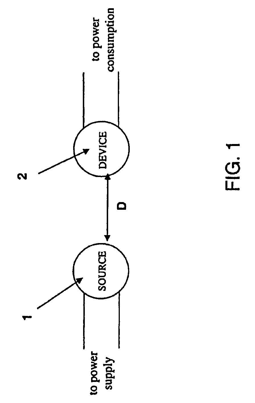
Radiative modes of omni-directional antennas, which work very well for information transfer, are not suitable for such energy transfer, because a vast majority of energy is wasted into free space.
Directed radiation modes, using lasers or highly-directional antennas, can be efficiently used for energy transfer, even for long distances (transfer distance LTRANS>>LDEV, where LDEV is the characteristic size of the device), but require existence of an uninterruptible line-of-sight and a complicated tracking system in the case of mobile objects.

Method used


Image

  • Wireless non-radiative energy transfer
  • Wireless non-radiative energy transfer
  • Wireless non-radiative energy transfer

Examples


Embodiment Construction

[0034]In contrast to the currently existing schemes, the invention provides the feasibility of using long-lived oscillatory resonant electromagnetic modes, with localized slowly evanescent field patterns, for wireless non-radiative energy transfer. The basis of this technique is that two same-frequency resonant objects tend to couple, while interacting weakly with other off-resonant environmental objects. The purpose of the invention is to quantify this mechanism using specific examples, namely quantitatively address the following questions: up to which distances can such a scheme be efficient and how sensitive is it to external perturbations. Detailed theoretical and numerical analysis show that a mid-range (LTRANS≈few*LDEV) wireless energy-exchange can actually be achieved, while suffering only modest transfer and dissipation of energy into other off-resonant objects.

[0035]The omnidirectional but stationary (non-lossy) nature of the near field makes this mechanism suitable for mob...


PUM


Abstract

The electromagnetic energy transfer device includes a first resonator structure receiving energy from an external power supply. The first resonator structure has a first Q-factor. A second resonator structure is positioned distal from the first resonator structure, and supplies useful working power to an external load. The second resonator structure has a second Q-factor. The distance between the two resonators can be larger than the characteristic size of each resonator. Non-radiative energy transfer between the first resonator structure and the second resonator structure is mediated through coupling of their resonant-field evanescent tails.

Description

CROSS-REFERENCE TO RELATED APPLICATIONS[0001]This application is a continuation and claims the benefit of priority under 35 USC § 120 to U.S. application Ser. No. 11 / 481,077 filed Jul. 5, 2006, which claims priority under 35 USC § 119(e) to U.S. provisional application Ser. No. 60 / 698,442 filed Jul. 12, 2005. The contents of the prior applications mentioned above are incorporated herein by reference in their entirety.STATEMENT AS TO FEDERALLY FUNDED RESEARCH[0002]This invention was made with government support awarded by the National Science Foundation under Grant No. DMR-0213282. The government has certain rights in this invention.BACKGROUND OF THE INVENTION[0003]The invention relates to the field of oscillatory resonant electromagnetic modes, and in particular to oscillatory resonant electromagnetic modes, with localized slowly evanescent field patterns, for wireless non-radiative energy transfer.[0004]In the early days of electromagnetism, before the electrical-wire grid was depl...

Claims


Application Information

Patent Timeline
Patent Type & Authority Applications(United States)
IPC IPC(8): H01P1/20H01P7/00
CPCB60L11/182H01Q9/04H02J5/005Y02T90/14Y02T10/7005Y02T10/7088Y02T90/122H02J17/00H02J50/12B60L53/126H02J50/40H02M3/01H02M1/0064H04B5/0037Y02T10/70Y02T10/7072H01P7/00Y02T90/12H01F38/14
Inventor JOANNOPOULOS, JOHN DKARALIS, ARISTEIDISSOLJACIC, MARIN
Owner MASSACHUSETTS INST OF TECH
Why Eureka
Try Eureka