Optical scanning device and image forming apparatus

a scanning device and image forming technology, applied in the field of optical scanning devices and image forming apparatuses, can solve the problems of increased time required for apc and difficulty in revealing image forming apparatuses

Inactive Publication Date: 2009-08-06
RICOH KK
View PDF34 Cites 31 Cited by
  • Summary
  • Abstract
  • Description
  • Claims
  • Application Information

AI Technical Summary

Benefits of technology

[0010]It is an object of the present invention to at least

Problems solved by technology

However, if the requirement of the high speed and the high density in the image forming apparatus becomes higher, it would be difficult for image forming apparatuses disclosed in the above Patent Documents to perform the APC with a sufficient accura

Method used


Image

  • Optical scanning device and image forming apparatus
  • Optical scanning device and image forming apparatus
  • Optical scanning device and image forming apparatus

Examples


Embodiment Construction

[0036]Exemplary embodiments of the present invention are explained in detail below with reference to the accompanying drawings.

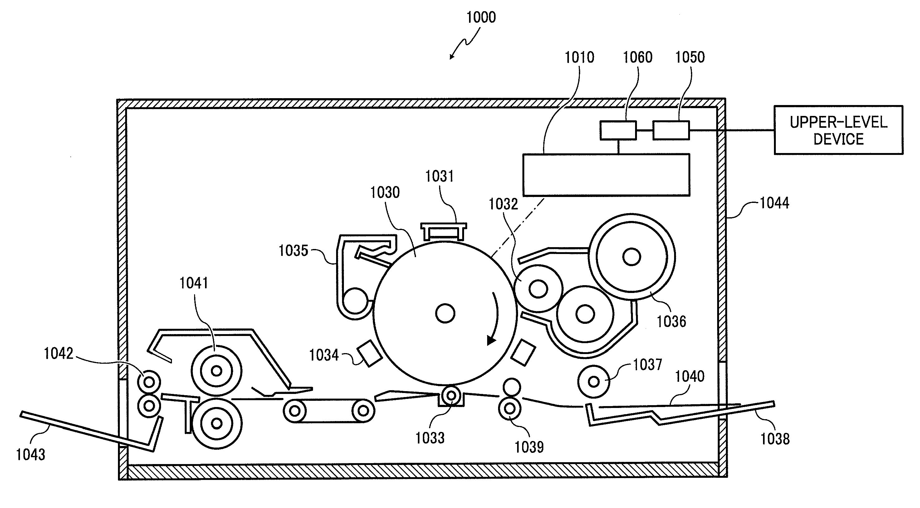
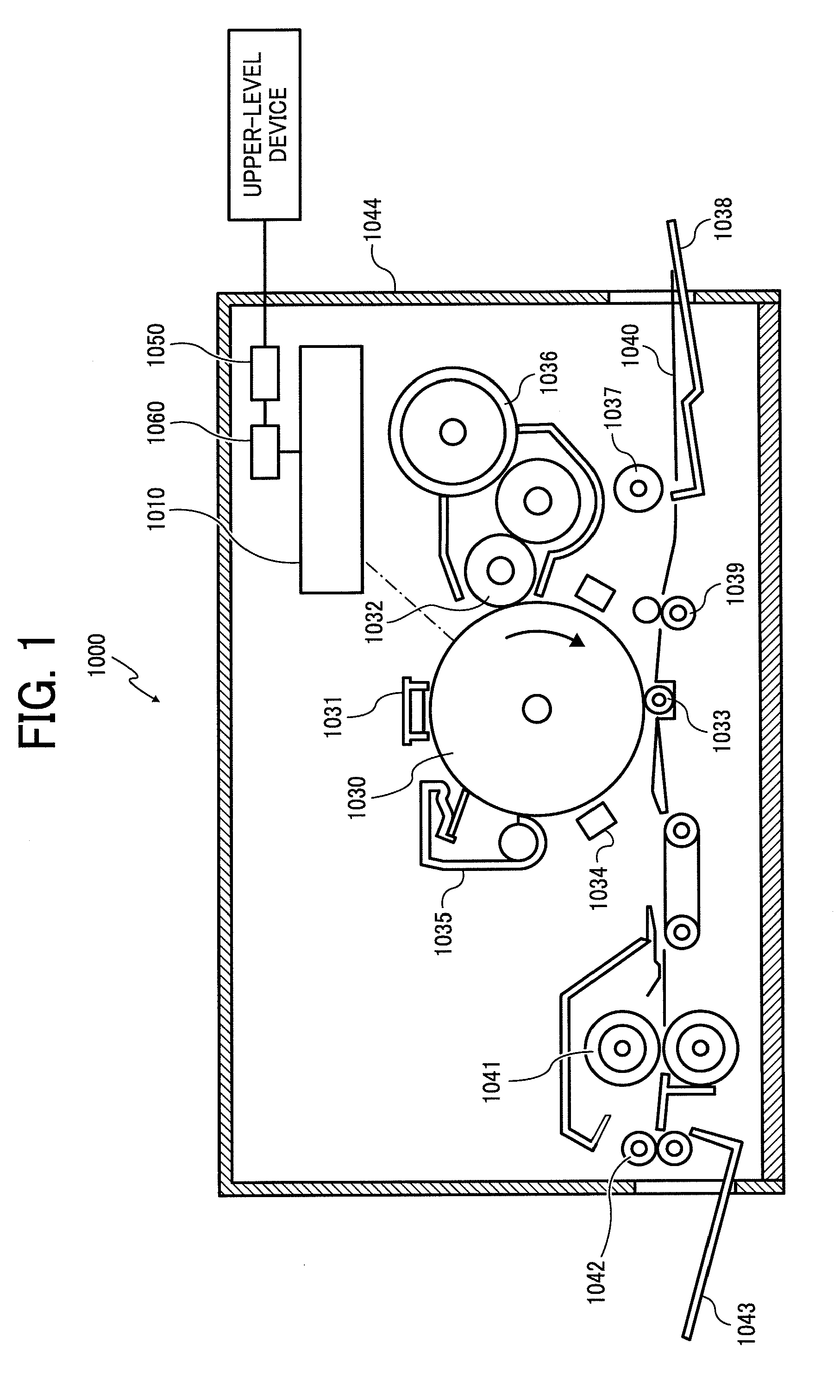
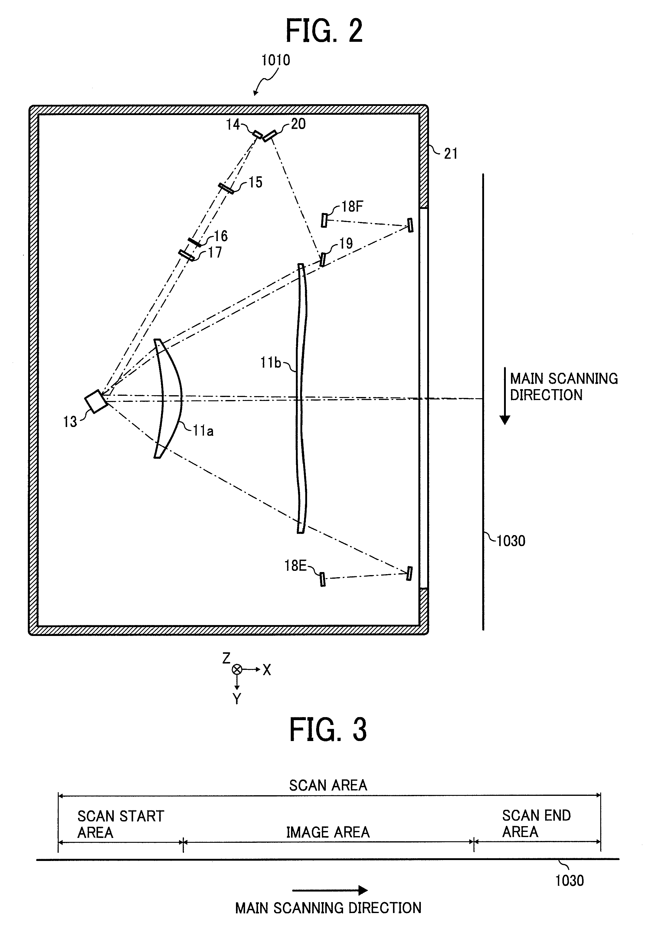
[0037]FIG. 1 is a schematic diagram of a laser printer 1000 as an image forming apparatus according to an embodiment of the present invention.

[0038]The laser printer 1000 includes an optical scanning device 1010, a photosensitive element 1030, a charging unit 1031, a developing roller 1032, a transfer charging unit 1033, a neutralizing unit 1034, a cleaning unit 1035, a toner cartridge 1036, a feeding roller 1037, a feed tray 1038, a pair of registration rollers 1039, a fixing roller 1041, a pair of discharging rollers 1042, a catch tray 1043, a communication control device 1050, and a printer control device 1060 that controls the above components. Each of the above components is arranged at a predetermined position in a printer casing 1044.

[0039]The communication control device 1050 controls a bidirectional communication with an upper-level device, such as ...


PUM


Abstract

A deflector deflects a light beam emitted from a light source including a plurality of light-emitting units. A scanning optical system focuses the light beam deflected by the deflector on a scanning target surface. A monitoring photoreceiver receives a part of a light beam deflected by the deflector and directed toward an area within a scanning area outside an image area. A detecting unit individually detects emission powers of at least two light-emitting units based on an output signal of the monitoring photoreceiver in a single sweep of scanning.

Description

CROSS-REFERENCE TO RELATED APPLICATIONS[0001]The present application claims priority to and incorporates by reference the entire contents of Japanese priority document 2008-025842 filed in Japan on Feb. 6, 2008.BACKGROUND OF THE INVENTION[0002]1. Field of the Invention[0003]The present invention relates to an optical scanning device and an image forming apparatus, and more particularly, to an optical scanning device that scans a target surface with a light beam and an image forming apparatus including the optical scanning device.[0004]2. Description of the Related Art[0005]In recent years, improvements in a print speed (high speed) and a writing density (high density) have been required in an image forming apparatus, such as a laser printer and a digital copier. To achieve the improvements in the print speed and the writing density, in a conventional technology, an optical scanning device is employed which includes a light source having a plurality of light-emitting elements, and a ...

Claims


Application Information

Patent Timeline
IPC IPC(8): B41J15/14
CPCG02B26/127
Inventor ISHIDA, MASAAKINIHEI, YASUHIROOMORI, ATSUFUMIOZASA, DANTANABE, JUN
Owner RICOH KK
Why Eureka
Try Eureka