Bone fixation device and method of use thereof

a bone fixation device and bone technology, applied in the field of bone fixation devices and methods, can solve the problems of increased diastasis and instability, and more serious cases may require surgery

Inactive Publication Date: 2009-08-06
SCHEMITSCH +1
View PDF4 Cites 73 Cited by
  • Summary
  • Abstract
  • Description
  • Claims
  • Application Information

AI Technical Summary

Benefits of technology

[0011]In some embodiments, the method further comprises selecting a connector such that the central portion is configured to deflect from the longitudinal axis when a force is applied transverse to the longitudinal axis

Problems solved by technology

Progressive disruption of these ligaments results in increased diastasis and instability Mild cases of ankle syndesmosis injury witho

Method used


Image

  • Bone fixation device and method of use thereof
  • Bone fixation device and method of use thereof
  • Bone fixation device and method of use thereof

Examples


Embodiment Construction

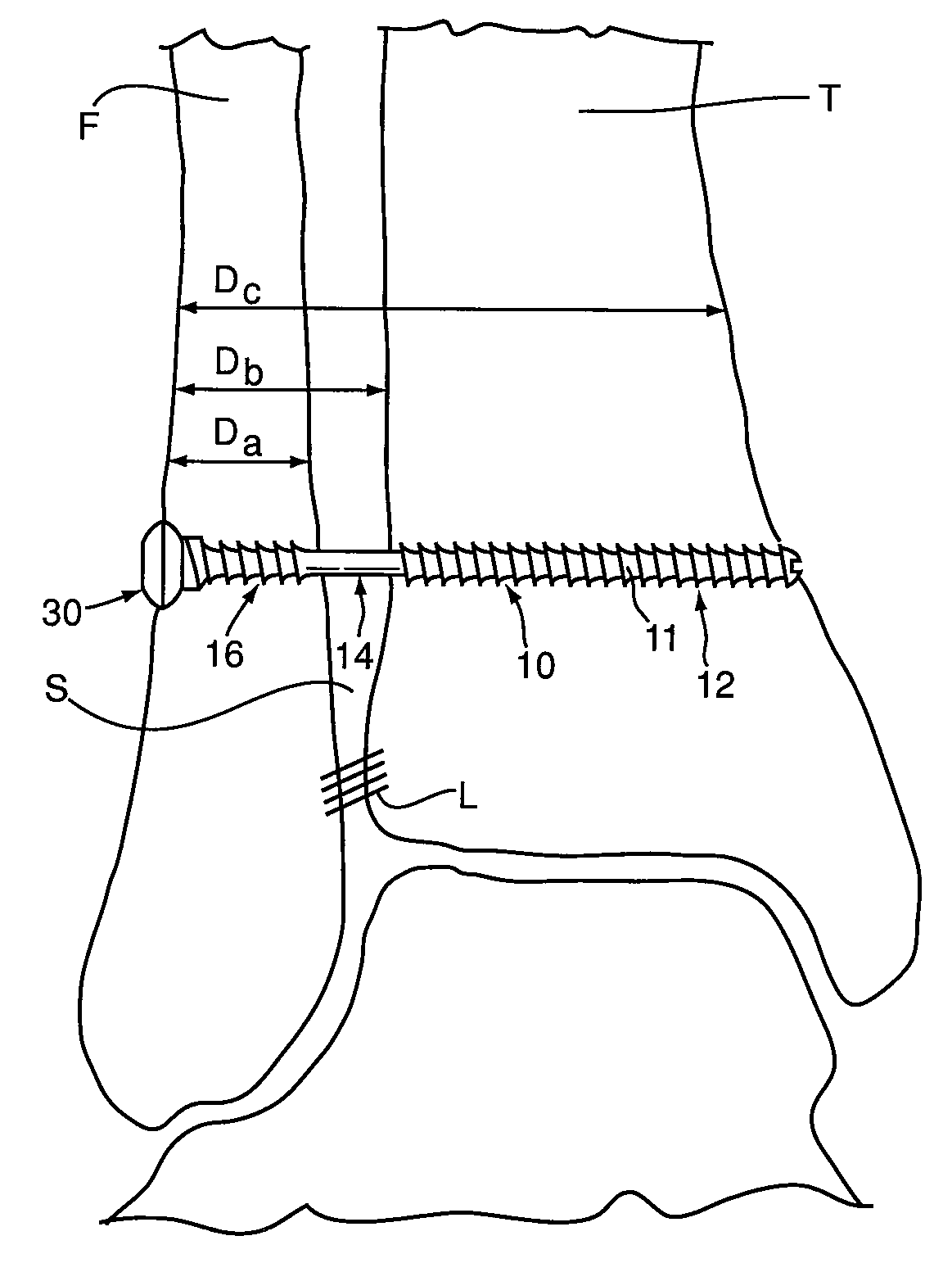
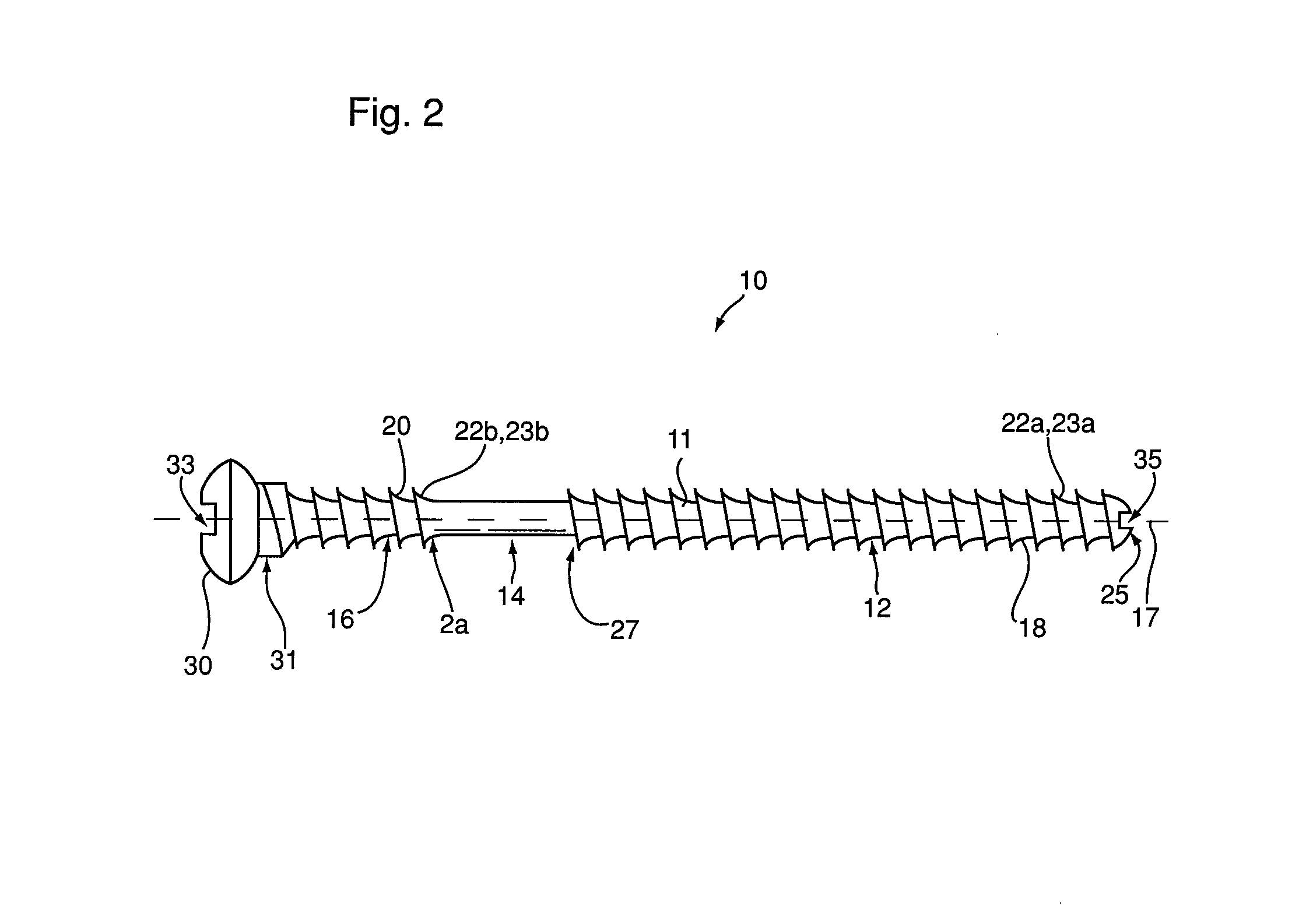
[0037]Referring to FIG. 2, an embodiment of a bone fixation device 10 of the present invention is shown. Bone fixation device 10 is a connector comprising a unitary body 11, and is configured to repair injuries, such as ankle syndesmosis injuries, by flexibly connecting two bones, such as the tibia and the fibula. Bone fixation device 10 has a longitudinally extending axis 17, and comprises a first portion 12, a central portion 14, and a second portion 16. Central portion 14 extends along axis 17 between first portion 12 and second portion 16. Bone fixation device 10 is configured such that in use, first portion 12 is secured to a first bone, second portion 16 is secured to a second bone, and at least a portion of central portion 14 extends between the bones.

[0038]In order to secure each of first portion 12 and second portion 16 to first and second bones, each of first portion 12 and second portion 16 preferably have an outer surface 18, 20 comprising at least one bone engagement me...


PUM


Abstract

A device for flexibly connecting bones, and a method of using the device for repairing a syndesmotic joint of an ankle are disclosed. The connector has, spaced sequentially, a first portion, a central portion and a second portion, and the portions define a longitudinally extending axis. The method comprises securing the first portion of the connector to a tibia of a patient proximate the syndesmotic joint, securing the second portion of the connector to a fibula of the patient proximate the syndesmotic joint, and, positioning at least a portion of the central portion having increased flexibility in the syndesmotic space.

Description

FIELD OF THE INVENTION[0001]The invention relates to a method and apparatus for fixation of bones. More specifically the invention relates to a device for flexibly connecting bones, and a method of using the device for repairing the syndesmotic joint of an ankle.BACKGROUND OF THE INVENTION[0002]The ankle syndesmosis (S) is the joint between the distal tibia (T) and the distal fibula (F), where the tibia and fibula are held together by connective ligaments (L), as shown in FIG. 1. At the ankle syndesmosis, the tibia and the fibula are supported and held together by interosseous membrane and three main ligaments: the anterior inferior tibiofibular ligament, the posterior inferior tibiofibular ligament, and the transverse ligament. During normal gait, the fibula moves with respect to the tibia. For example, referring to FIG. 1, body weight and muscle contraction during walking actively pulls the fibula (F) downward relative to the tibia (T), in a direction indicated by arrow A1. Additi...

Claims


Application Information

Patent Timeline
IPC IPC(8): A61B17/56A61B19/00
CPCA61B17/8625A61B17/863A61B2017/00867A61B17/866A61B2017/00862A61B17/8635
Inventor CHIU, MARK HSIEN NIEN
Owner SCHEMITSCH
Why Eureka
Try Eureka