Fortified cannulated screw

a cannulated screw and fortified technology, applied in the field of methods and medical devices, can solve the problems of deformation of a traditional cannulated screw, unwise cannulated screw, and small bones that are generally not tolerant of multiple drill holes used to accurately and precisely

Inactive Publication Date: 2009-08-06
MANDERSON EASTON L
View PDF11 Cites 92 Cited by
  • Summary
  • Abstract
  • Description
  • Claims
  • Application Information

AI Technical Summary

Benefits of technology

[0009]A cannulated screw is provided having internal threads in a lumen to accommodate a fortifying screw. The fortifying screw is screwed into the threads in the lumen of the cannulated screw after the cannulated screw has been accurately placed in the bone by following a guide pin or guide wire to the desired location is as is commonly done with cannulated screws. The fortifying screw fortifies the cannulated screw and gives it strength approximately equal to that of a solid screw.
[0012]provide a cannulated screw that is easy to implant; and

Problems solved by technology

But, small bones are generally not tolerant to multiple drill holes used to accurately and precisely place screws.
Where the screws used to heal fractures in such bone are small, weight-bearing may cause deformation of a traditional cannulated screw.
For example, cannulated screws up to 7.0 mm in diameter lack the strength of solid screws of similar diameters because of their hollow cross section and long lengths Therefore, in some fractures where a cannulated screw could be placed accurately over a guide wire in order to aid in the placement of the screw, the lack of strength of the cannulated screw itself may make choosing such a cannulated screw unwise.

Method used


Image

  • Fortified cannulated screw
  • Fortified cannulated screw
  • Fortified cannulated screw

Examples


Embodiment Construction

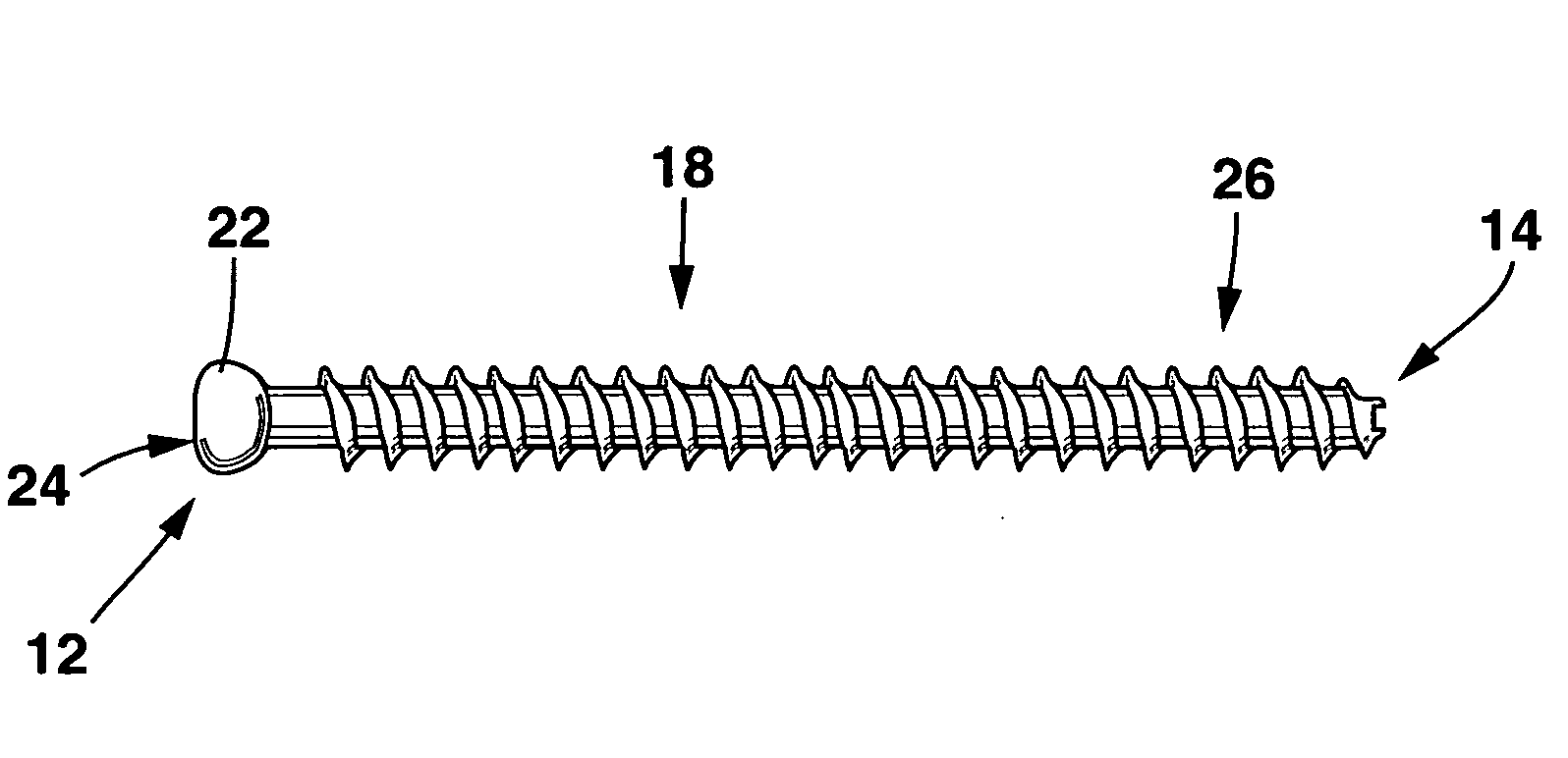
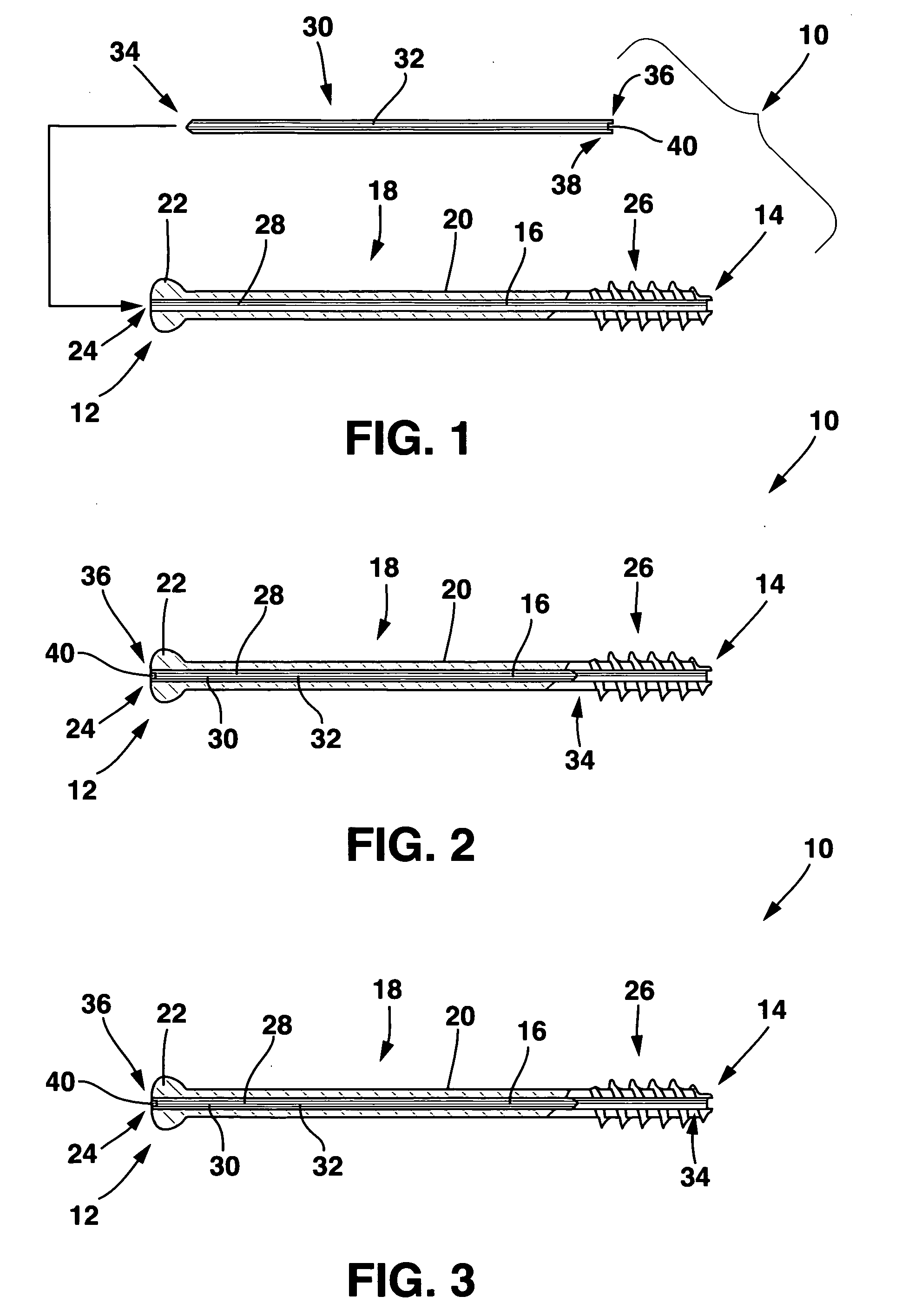
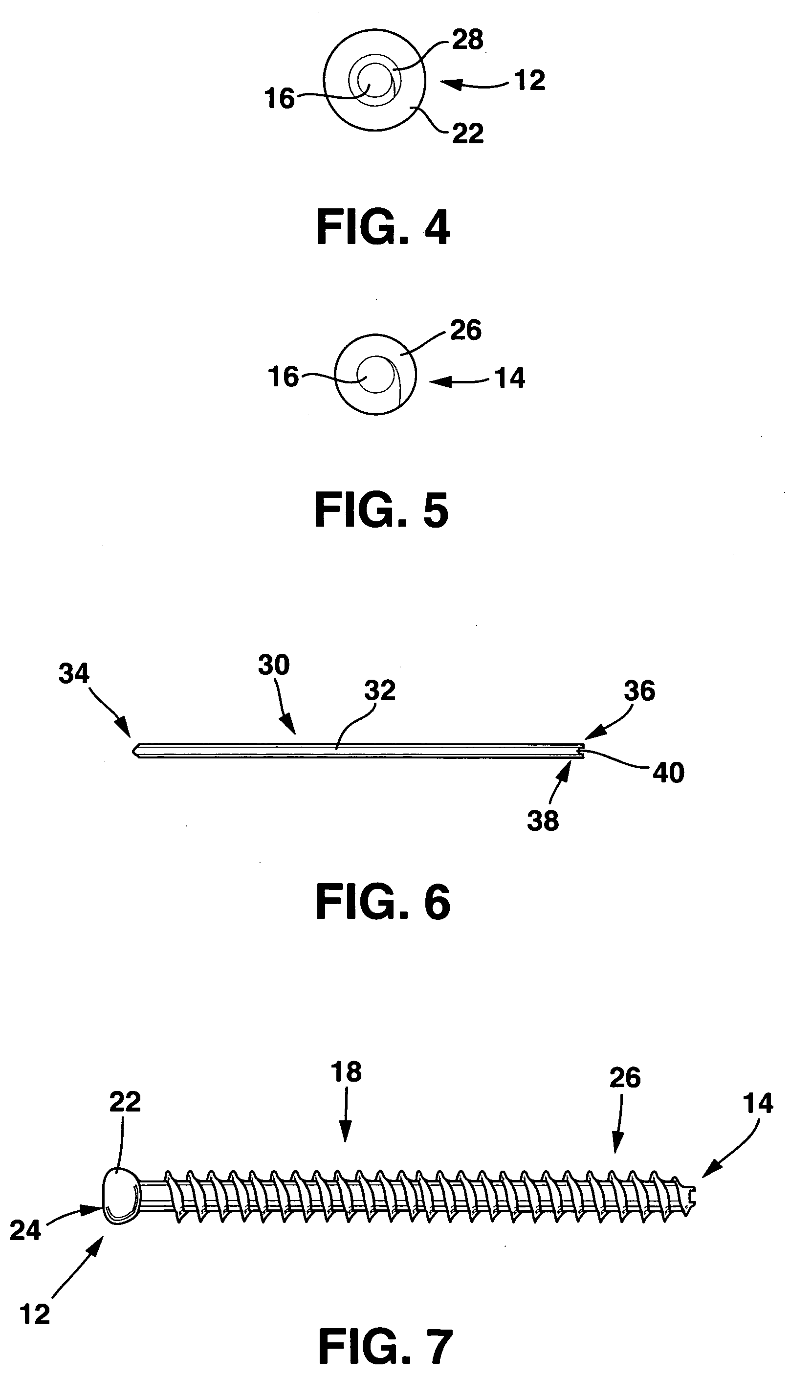
[0024]In order that the invention may be clearly understood and readily carried into effect, preferred embodiments of the invention will now be described, by way of example only and not to limit the invention, with reference to the accompanying drawings. The fortified cannulated screw of the present invention is shown in the drawings generally labeled 10.

[0025]The fortified cannulated screw 10 has a proximal end 12, a distal end 14, a lumen 16 and a shaft 18 having an outer surface 20. The shaft 18 extends from the proximal end 12 to the distal end 14 and contains the lumen 16.

[0026]The proximal end 12 of the fortified cannulated screw 10 preferably includes a head 22. The head 22 typically has a slightly larger diameter than the diameter of the shaft 18. In a preferred embodiment of the head 22, the head 22 includes means for interacting with a tool for screwing the fortified cannulated screw 10 into the bone. An example of such means is screw slot 24 formed in the lumen 16 at the ...


PUM


Abstract

A cannulated screw is provided having internal threads in a lumen to accommodate a fortifying screw. The fortifying screw is screwed into the threads in the lumen of the cannulated screw after the cannulated screw has been accurately placed in the bone by following a guide pin or guide wire to the desired location is as is commonly done with cannulated screws. The fortifying screw fortifies the cannulated screw and gives it strength approximately equal to that of a solid screw.

Description

BACKGROUND OF THE INVENTION[0001]1. Field of the Invention[0002]The present invention relates generally to methods and medical devices that connect together fractured bone or fuse bones of one or more joints.[0003]2. Description of Related Art[0004]Surgical screws are now commonly used to repair bone fractures or to fuse bones of a joint together. For example, in intertrochanteric fractures, that is, fractures of the femur below the neck of the femur, a common treatment is to use a screw and plate device to hold the two fragments in position while the fracture heals. In this process, the surgeon inserts a large screw into the femoral head across the fracture. The plate is positioned down the shaft of the femur and secured in place by smaller screws that pass into the femur.[0005]Bone fractures of all types may occur where the fracture is located close to nerves or blood vessels. When placing screws into the bone to treat the fracture, it is important that the screws stay away from a...

Claims


Application Information

Patent Timeline
Patent Type & Authority Applications(United States)
IPC IPC(8): A61B17/56
CPCA61B17/8685A61B17/864
Inventor MANDERSON, EASTON L.
Owner MANDERSON EASTON L
Why Eureka
Try Eureka