Robot safety monitor device, and robot safety monitor method

a safety monitor and robot technology, applied in the direction of electrical programme control, program control, instruments, etc., can solve the problems of insufficient safety monitoring, natural differences, and no technology that improves safety in conjunction with the change of tools, so as to improve the safety of robots

Inactive Publication Date: 2009-08-06
JTEKT CORP
View PDF21 Cites 20 Cited by
  • Summary
  • Abstract
  • Description
  • Claims
  • Application Information

AI Technical Summary

Benefits of technology

[0009]The invention realizes a robot safety monitor device and a robot safety monitor method that improve the safety of a robot during tool change.
[0015]The effects achieved by the first aspect of the invention are as follows. That is, according to the first aspect of the invention, in conjunction with tool change, the first tool identification information that is output from the robot control device in real time, and the second tool identification information that is the identification information of a detected tool that is actually attached to a hand of the robot are input to the robot safety monitor device. Therefore, with regard to the tool change of the robot, information is provided in a redundant manner, and therefore correct tool information can be determined by equality between two pieces of tool information. Thus, safety improves. Besides, even if the first tool identification information and the second tool identification information are not equal, the emergency stop signal is not output until the position coordinates of the taught reference point go out of the predetermined region with the unequalness therebetween maintained. Therefore, even if the first tool identification information and the second tool identification information are unequal, the emergency stop signal is not output in the case where the position coordinates of the taught reference point are within the predetermined region. Of course, if the first tool identification information and the second tool identification information become equal to each other while the position coordinates of the taught reference point are located within the predetermined region, the emergency stop signal is not output. Thus, by properly setting the predetermined region in a region where safety is secured for a worker, it is possible to secure safety while the two pieces of tool identification information are unequal. Then, the provision of tool information in a redundant manner will allow improvement of the safety regarding tool change, and will exclude an unnecessary emergency stop that is caused by unequalness of two pieces of tool information. Thus, safety and work efficiency can both be improved.
[0016]Besides, the region setting portion may be constructed so as to set as reference coordinates the position coordinates of the taught reference point that are calculated by the position coordinates calculation portion as occurring at a time when unequalness between the first tool identification information and the second tool identification information is first detected by the determination portion, and so as to set a region that contains the reference coordinates as the predetermined region. Usually, the tool change is performed at a position that is safe for the worker. It is considered that at the time of tool change, the taught reference point will hardly move, and the posture thereof will not greatly change. Therefore, it is considered to be the start of a tool change when the first tool identification information and the second tool identification information are first unequal to each other. Therefore, if the position coordinates of the taught reference point at the time of start are set as reference coordinates and a region that contains the reference coordinates is set as a predetermined region, the amount of movement of the taught reference point at the time of tool change can be properly restricted. Besides, if the two pieces of tool identification information are unequal to each other when the taught reference point goes out of the predetermined region for the first time, the emergency stop signal is output for the first time. In this manner, safety can be properly improved.
[0017]Besides, the predetermined region may be set as a tool change region in the actual space. In this case, if the two pieces of tool identification information are unequal in a tool change region that has high safety, it can be considered that the tool change is being performed at a proper location that has high safety, and therefore the emergency stop signal is not allowed to be output. If the two pieces of tool identification information remain unequal even after the taught reference point goes out of the predetermined region, the emergency stop signal is output for the first time. In this manner, safety can be properly improved.
[0018]Besides, even in the case where the taught reference point exists within the predetermined region during the period during which the two pieces of tool identification information are unequal, the emergency stop signal may be output if the moving velocity of the taught reference point is greater than or equal to a predetermined value. At the time of tool change, the moving velocity of the taught reference point is considered to be slow. Therefore, even if while the two pieces of tool identification information are unequal, the taught reference point exists within the predetermined region where safety is secured, it is conceivable that the moving velocity of the taught reference point has increased for some cause. Therefore, by outputting the emergency stop signal in such a case, safety can be further improved.

Problems solved by technology

However, the foregoing technologies of Japanese Patent No. 2662864 and Published Japanese Translation of PCT application No. 2001-525263 (JP-A-2001-525263) are designed to monitor the movement path of a taught reference point, such as a tool's distal end, or the like, and no technology that improves the safety in conjunction with the change of tools has been developed.
However, the time when the attachment of a tool to a flange of the robot is completed is naturally different from the time point at which the robot control device outputs the identification information of the new tool.
This gives rise to a problem of the safety monitoring becoming insufficient.
Therefore, if despite a tool change, the position of the distal end of the old tool or the like is still used as a basis for performing the position control or the safety monitoring, that position is different from the actual position of the distal end of the presently used tool, thus giving rise to a problem in safety.
However, as for the robot safety monitor device, a time difference occurs between the tool identification information output from the robot control device, and the real tool attachment completion signal and the tool identification information that are newly input.

Method used


Image

  • Robot safety monitor device, and robot safety monitor method
  • Robot safety monitor device, and robot safety monitor method
  • Robot safety monitor device, and robot safety monitor method

Examples


embodiment 1

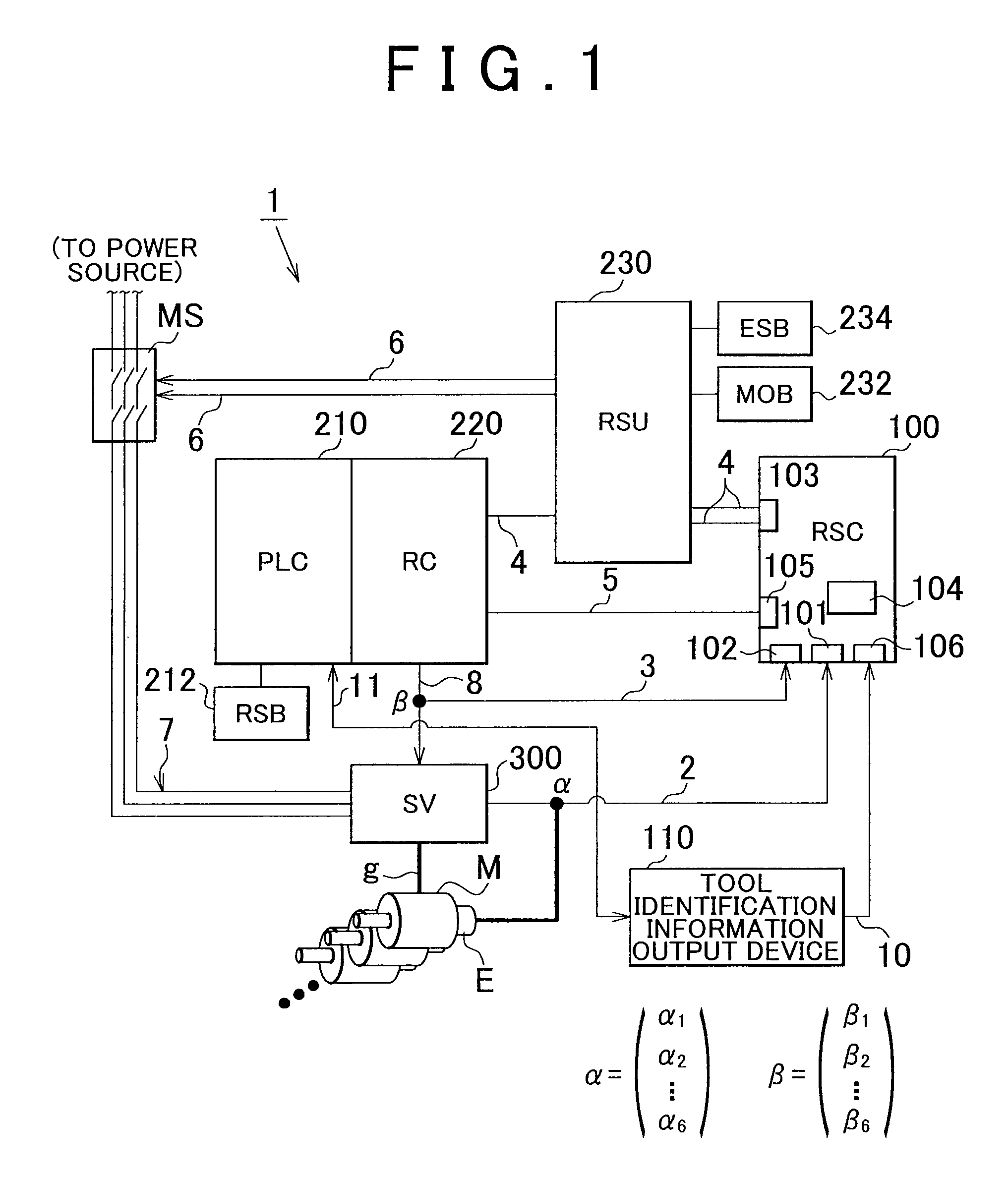
[0030]FIG. 1 shows a main construction of a robot drive control system 1 of Embodiment 1. The robot drive control system 1 is constructed mainly of a robot safety unit (RSU, also termed a safety PLC) 230, a robot control device (robot controller (RC)) 220, a programmable logic controller (PLC) 210, a safety monitor device (robot safety controller (RSC)) 100, a servo unit 300, and a tool identification information output device 110. The robot control device 220, the robot safety unit 230, and the safety monitor device 100 are interconnected by a bus 4. Besides, the PLC 210 and the robot control device 220 are connected to each other by an internal bus. The robot control device 220 and the safety monitor device 100 are interconnected by a communication line 3 and a communication line 5. The robot control device 220 and the servo unit 300 are interconnected by a communication line 8. The servo unit 300 and the safety monitor device 100 are interconnected by a communication line 2. The ...

example 2

[0055]In Embodiment 1, a predetermined region is set by using, as a reference, the position coordinates of the taught reference point at the time when the two pieces of tool identification information become unequal to each other for the first time. Therefore, if the movement region of the taught reference point in the actual space is restricted in a time section in which two pieces of tool identification information are unequal regardless of at what position the tool change position is in the actual space, it is assumed that safety is secured even though the two pieces of tool identification information are unequal. In Embodiment 2, on the other hand, the tool change position in the actual space is known beforehand, and therefore the predetermined region V is not relatively determined with reference to the reference coordinates S, but is defined in absolute coordinates in the actual space. It suffices that if the predetermined region is one sphere, the center coordinates and the ra...

example 3

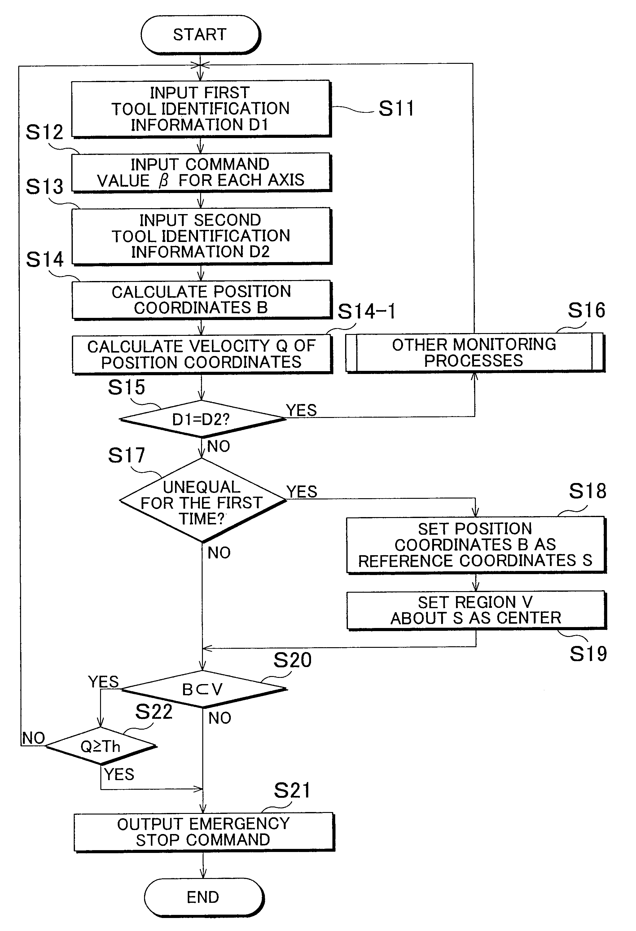
[0056]In Embodiments 1 and 2, no consideration is given to the moving velocity of the taught reference point during a period during which the two pieces of tool identification information are unequal. In Embodiment 3, the moving velocity of the taught reference point is further considered. A process procedure of the safety monitor device 100 as shown in FIG. 8 will be described. Steps S1 to S14 of the process procedure shown in FIG. 8 are substantially the same as those in Embodiment 1. In step S14-1, the moving velocity Q of the position coordinates B is computed from the position coordinates B computed in the past and the elapsed time. Step S15 to S20 of the process procedure in FIG. 8 are the same as those in Embodiment 1. In the case where the two pieces of tool identification information are unequal and the position coordinates S of the taught reference point exist in the predetermined region V, the answer to the determination in step S20 is YES, and subsequently it is determin...


PUM


Abstract

It is determined whether the first tool identification information that is output from a robot control device, and that indicates a present tool and the second tool identification information for detecting and identifying a tool attached to the robot are unequal to each other. The position coordinates of the taught reference point in an actual space of the robot occurring at the time when the unequalness therebetween is first detected are set as reference coordinates, and a region that contains the reference coordinates is set as a predetermined region. If the position coordinates of the taught reference point have come to exist outside the predetermined region during a period during which it is determined that the foregoing two pieces of information are unequal, an emergency stop signal for causing the robot to be in a safe state is output.

Description

INCORPORATION BY REFERENCE[0001]The disclosure of Japanese Patent Application No. 2008-024780 filed on Feb. 5, 2008 including the specification, drawings and abstract is incorporated herein by reference in its entirety.BACKGROUND OF THE INVENTION[0002]1. Field of the Invention[0003]The invention relates to a robot safety monitor device and a robot safety monitor method that monitor safety at the time of a tool change of a robot.[0004]2. Description of the Related Art[0005]Robot safety monitor devices for monitoring whether or not a movement path of a taught reference point of a robot is within a predetermined safe range that does not interfere with other objects, for example, the devices described in Japanese Patent No. 2662864 and Published Japanese Translation of PCT application No. 2001-525263 (JP-A-2001-525263), etc., have been widely known. In these devices, the robot is emergently stopped if the taught reference point where the robot receives a movement command is not within a...

Claims


Application Information

Patent Timeline
Patent Type & Authority Applications(United States)
IPC IPC(8): G05B19/048
CPCG05B2219/50198Y10T483/11G05B2219/40375G05B2219/50275G05B2219/39399G05B2219/43203B25J9/1674Y10T483/134Y10T483/10G05B2219/40228
Inventor KOMURO, KATSUHIROAONO, TOSHIO
Owner JTEKT CORP
Why Eureka
Try Eureka