Walking assisting device

Active Publication Date: 2009-08-13
HONDA MOTOR CO LTD
View PDF4 Cites 24 Cited by
  • Summary
  • Abstract
  • Description
  • Claims
  • Application Information

AI Technical Summary

Benefits of technology

[0010]When the lateral swings of the left and right leg links are allowed as described above, however, the following defects will occur. Specifically, in a one-leg supporting state, the seat member is affected by a rolling moment around the lateral swing fulcrum of the leg link on the side of a supporting leg (a leg with the foot on the floor) due to the weight of the leg link on the side of an idling leg (a leg with the foot off the floor), which causes the rolling of the seat member. To resolve the above defect, the connecting portions on the undersurface of the seat member are preferably formed in such a way that the lateral swing fulcrum of one of the left and right leg links and the lateral swing fulcrum of the other leg link are located on the same axis line in forward and backward direction. According thereto, even if the weight of the leg link on the side of the idling leg is applied to the seat member in the one-leg supporting state, the seat member is not affected by the rolling moment around the lateral swing fulcrum of the leg link on the side of the supporting leg since the lateral swing fulcrum of the leg link on the side of the idling leg which is a weight-applied portion is located on the same axis line as the lateral swing fulcrum of the leg link on the side of the supporting leg. Therefore, it is possible to prevent the rolling of the seat member in the one-leg supporting state.
[0011]Where the ground contact member to which each foot of the user is attached is connected to each leg link at the lower end via the joint, the line of action of the supporting force of the leg link matches the line between the joint and the connecting portion. If the lateral distance between the joint and the connecting portion gets longer, the lateral component of the supporting force increases, which thereby increases the lateral force applied to the ground contact member and the seat member and makes the ground contact member and the seat member unstable. In this case, by disposing the joint laterally inside of the center of the width of the ground contact member, the lateral distance between the joint and the connecting portion is reduced, which decreases the lateral force acting on the ground contact member and the seat member and secures the stability.
[0012]If the leg link has a middle joint moving in such a way as to change a distance between the ground contact member and the seat member, the leg link can follow the change in distance between the foot and the crotch caused by bending and stretching of the knee joint of each user's leg. I

Problems solved by technology

Furthermore, the first joints of the left and right leg links project on both sides of the user's waist, and therefore the user easily hits his hands against the first joints or the upper parts of the leg links connected to the first joints when swinging his arms in walking, thereby reducing usabil

Method used


Image

  • Walking assisting device
  • Walking assisting device
  • Walking assisting device

Examples


Embodiment Construction

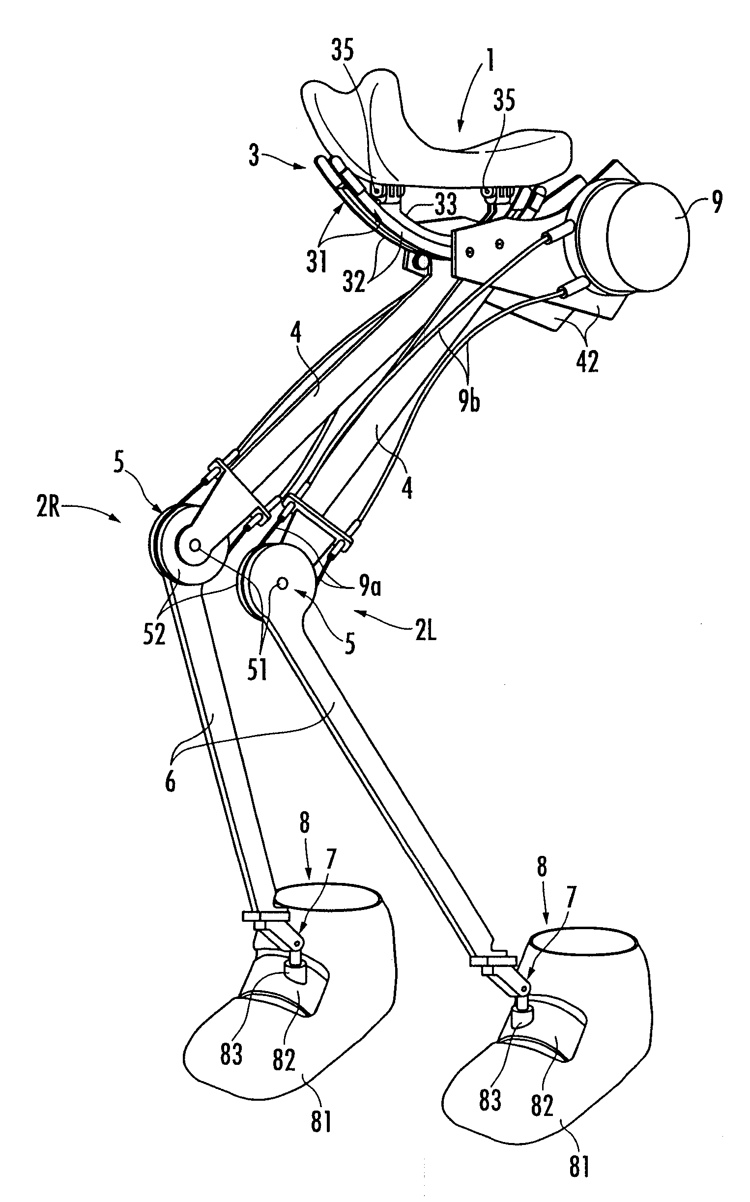
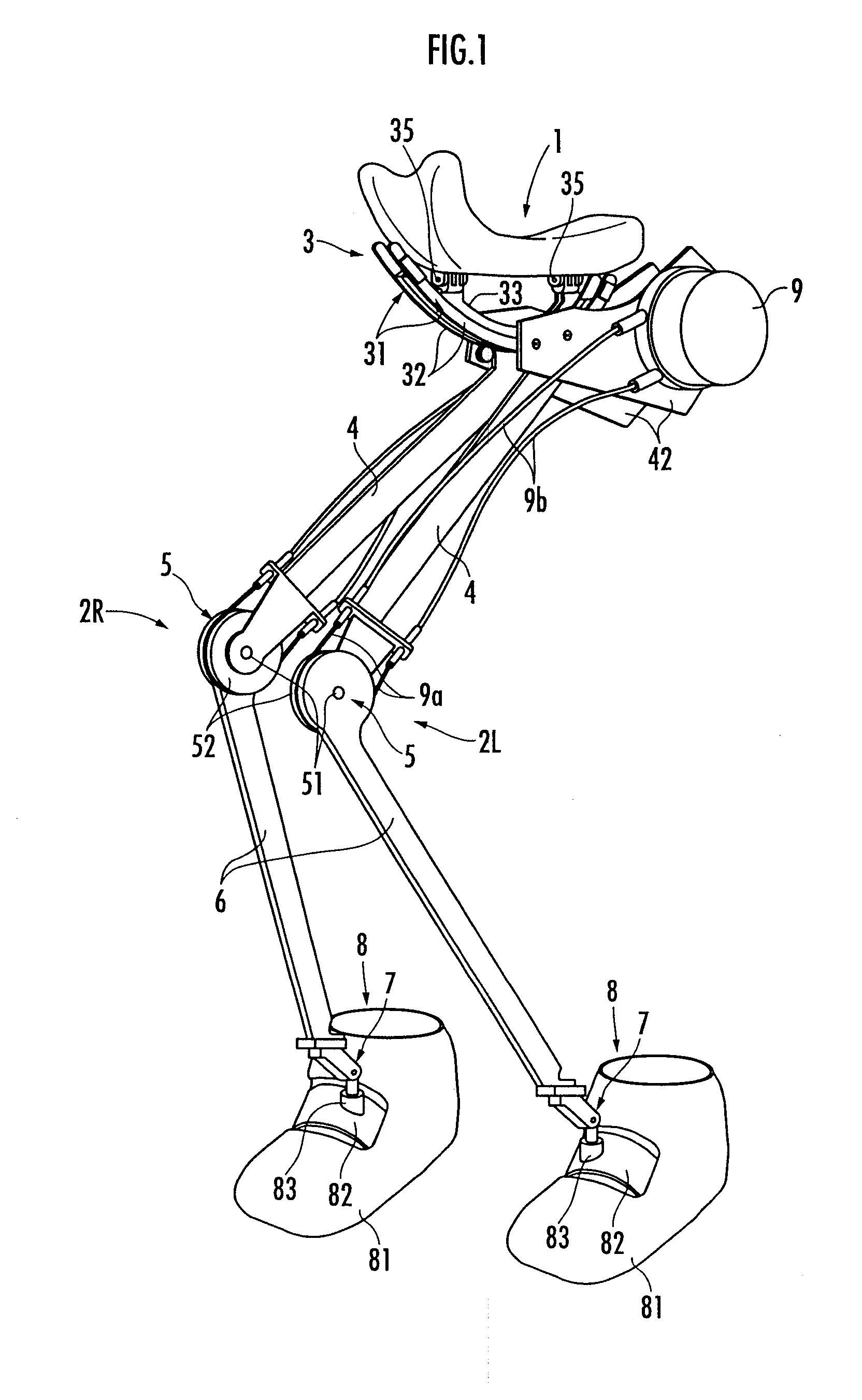
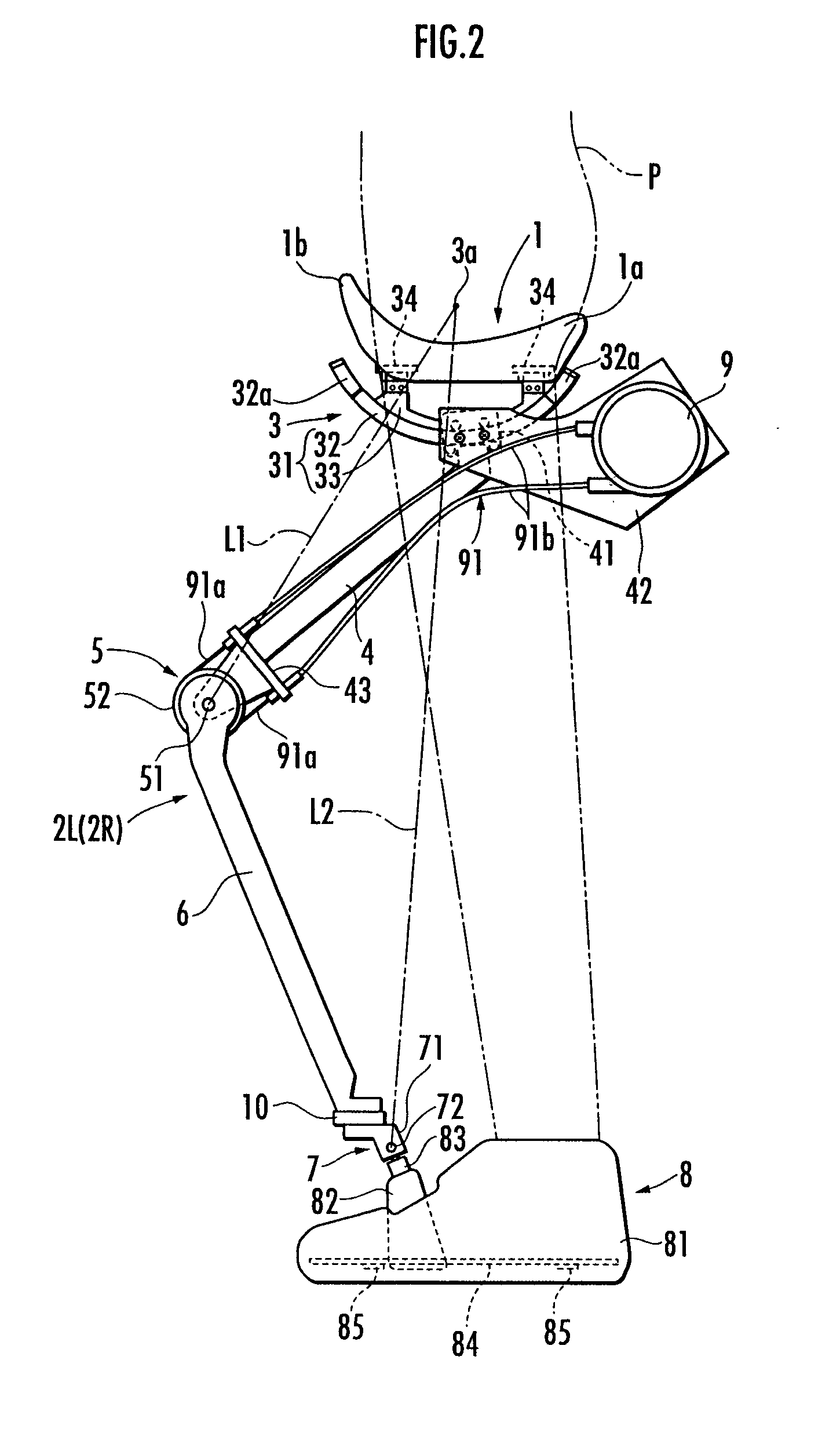
[0026]A walking assisting device according to preferred embodiments of the present invention will be described hereinafter. As shown in FIG. 1 to FIG. 3, the walking assisting device includes a seat member 1 serving as a load transfer portion which a user P sits astride and a pair of left and right leg links 2L and 2R arranged under the seat member 1.

[0027]The leg links 2L and 2R are each composed of a freely bending and stretching link, which has a first link 4 connected to a first joint 3 serving as a connecting portion attached to the undersurface of the seat member 1 and a second link 6 connected to the lower end of the first link 4 via a rotary second joint 5. Furthermore, the lower end of the second link 6 is connected to a ground contact member 8 attached to a user's left or right foot via a third joint 7. The leg links 2L and 2R are each equipped with a driving source 9 for the second joint 5. A rotational drive of the second joint 5 caused by the driving source 9 applies a ...


PUM


Abstract

A compact and easy-to-use walking assisting device capable of reducing constrained feeling given to a user and allowing a free swing of the arms of the user in walking. The walking assisting device comprises one or more leg links to which ground contact members are connected at their lower ends respectively and a load transfer portion connected to the upper ends of the leg links, in which at least a part of the weight of the user is supported by the leg links via the load transfer portion, wherein the load transfer portion includes a seat member for the user to sit astride, wherein connecting portions with the upper ends of the leg links connected thereto are attached to the undersurface of the seat member, and wherein the connecting portion have a degree of freedom allowing the forward/backward and lateral swings of the leg links.

Description

TECHNICAL FIELD[0001]The present invention relates to a walking assisting device for assisting walking by reducing load on user's legs.BACKGROUND ART[0002]Conventionally, as this type of walking assisting device, there is known one including a pair of left and right leg links connected to ground contact members attached to the user's left and right feet at their lower ends respectively and a load transfer portion connected to the upper ends of the leg links, wherein at least a part of the user's weight is supported by the leg links via the load transfer portion to reduce load on the user's legs so as to assist the user in walking (for example, refer to Japanese Patent Laid-Open No. 2003-220102). In this structure, the load transfer portion includes a waist support belt attached around the user's waist with the left and right leg links connected to the load transfer portion via first joints corresponding to human hip joints on both sides of the waist support belt in the lateral direc...

Claims


Application Information

Patent Timeline
IPC IPC(8): A61H3/00A61H3/02
CPCA61H1/0237A61H2201/149A61H3/008A61H2201/1633A61H2201/165A61H2201/50A61H2201/5061A61H2201/5071B25J9/0006A61H2201/0192A61H2201/1215A61H2201/1409A61H2201/1642A61H2201/1664A61H2201/1676A61H3/00
Inventor HIKI, YUTAKA
Owner HONDA MOTOR CO LTD
Why Eureka
Try Eureka